NPT Thread Chart 2026 – Sizes, OD, TPI & Taper Reference
NPT Thread Chart
Sizes, OD, TPI & Taper Reference
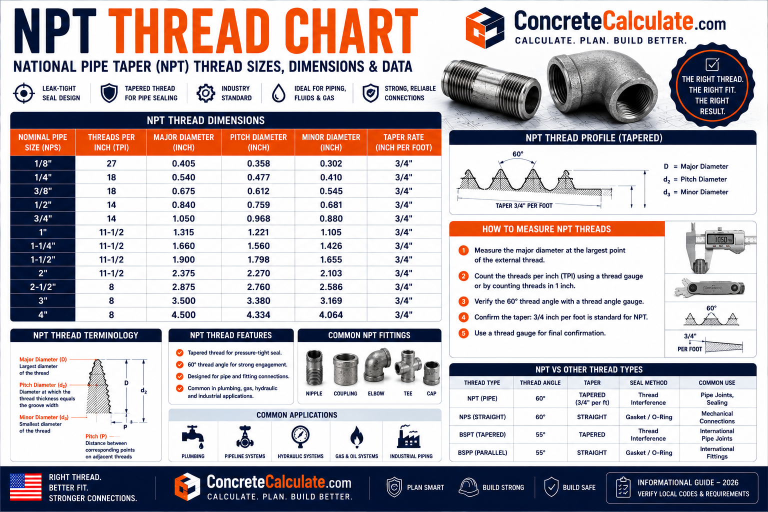
1/2 NPT does not have a 1/2 inch outside diameter. This chart explains why, with complete ASME B1.20.1 based dimensions, taper, engagement, and tap drill data.
 Reviewed by Muhammad Ramzan Babar, PhD Researcher & Calculator Developer · View Profile
Nominal NPT size is a standardized designation, not a measurement. 1/2 NPT has an actual outside diameter of approximately 0.840 inches, not 0.500 inches. Never assume nominal pipe size equals measured thread diameter.
⭐⭐⭐ NPT Thread Chart: Quick Reference
Dimensions reflect ASME B1.20.1, the governing U.S. standard for NPT and related general purpose inch pipe threads.
| NPT Size | Actual Pipe OD (in) | TPI | Pitch (in) | Thread Type | Taper |
|---|---|---|---|---|---|
| 1/16″ | 0.3125 | 27 | 0.0370 | NPT | 1:16 |
| 1/8″ | 0.4050 | 27 | 0.0370 | NPT | 1:16 |
| 1/4″ | 0.5400 | 18 | 0.0556 | NPT | 1:16 |
| 3/8″ | 0.6750 | 18 | 0.0556 | NPT | 1:16 |
| 1/2″ | 0.8400 | 14 | 0.0714 | NPT | 1:16 |
| 3/4″ | 1.0500 | 14 | 0.0714 | NPT | 1:16 |
| 1″ | 1.3150 | 11.5 | 0.0870 | NPT | 1:16 |
| 1-1/4″ | 1.6600 | 11.5 | 0.0870 | NPT | 1:16 |
| 1-1/2″ | 1.9000 | 11.5 | 0.0870 | NPT | 1:16 |
| 2″ | 2.3750 | 11.5 | 0.0870 | NPT | 1:16 |
| 2-1/2″ | 2.8750 | 8 | 0.1250 | NPT | 1:16 |
| 3″ | 3.5000 | 8 | 0.1250 | NPT | 1:16 |
| 4″ | 4.5000 | 8 | 0.1250 | NPT | 1:16 |
All dimensions reflect ASME B1.20.1, American National Standard Pipe Threads (General Purpose), which specifically covers NPT and related general purpose inch pipe thread forms including NPS and NPTR.
⭐ What Is NPT Thread?
NPT stands for National Pipe Taper, a standardized tapered pipe thread system.
National Pipe Taper
An inch based, tapered thread form used for pipe and fitting connections, defined by ASME B1.20.1.
Tapered thread
Unlike ordinary fastener threads, NPT diameter decreases progressively along its length rather than staying constant.
Sealing function
The taper causes increasing metal-to-metal interference as the fitting is tightened, which is a core part of how NPT connections seal.
NPT is not a fastener thread
NPT is fundamentally different from UNC or UNF bolt threads, which are straight, parallel, and not designed primarily to seal against pressure.
⭐⭐⭐ NPT Nominal Size vs Actual Diameter
This is the single most misunderstood fact about NPT threads.
1/2 NPT does not have a 0.500 inch outside diameter. Its actual outside diameter is approximately 0.840 inches. This gap between nominal designation and measured dimension exists across every NPT size and is the leading cause of NPT identification confusion.
| Nominal NPT Size | What You Might Expect | Actual Outside Diameter |
|---|---|---|
| 1/4″ | 0.250 in | 0.540 in |
| 3/8″ | 0.375 in | 0.675 in |
| 1/2″ | 0.500 in | 0.840 in |
| 3/4″ | 0.750 in | 1.050 in |
| 1″ | 1.000 in | 1.315 in |
Nominal pipe size historically traces back to the approximate internal bore of older pipe standards, not the thread’s actual outside diameter. Never assume nominal size equals measured diameter for any NPT part.
⭐⭐⭐ NPT Thread Dimensions Chart
The complete engineering reference table covering every commonly used NPT size.
| Nominal Size | Pipe OD (in) | Pipe OD (mm) | TPI | Pitch (in) | Pitch (mm) |
|---|---|---|---|---|---|
| 1/16″ | 0.3125 | 7.94 | 27 | 0.0370 | 0.941 |
| 1/8″ | 0.4050 | 10.29 | 27 | 0.0370 | 0.941 |
| 1/4″ | 0.5400 | 13.72 | 18 | 0.0556 | 1.411 |
| 3/8″ | 0.6750 | 17.14 | 18 | 0.0556 | 1.411 |
| 1/2″ | 0.8400 | 21.34 | 14 | 0.0714 | 1.814 |
| 3/4″ | 1.0500 | 26.67 | 14 | 0.0714 | 1.814 |
| 1″ | 1.3150 | 33.40 | 11.5 | 0.0870 | 2.209 |
| 1-1/4″ | 1.6600 | 42.16 | 11.5 | 0.0870 | 2.209 |
| 1-1/2″ | 1.9000 | 48.26 | 11.5 | 0.0870 | 2.209 |
| 2″ | 2.3750 | 60.32 | 11.5 | 0.0870 | 2.209 |
| 2-1/2″ | 2.8750 | 73.02 | 8 | 0.1250 | 3.175 |
| 3″ | 3.5000 | 88.90 | 8 | 0.1250 | 3.175 |
| 3-1/2″ | 4.0000 | 101.60 | 8 | 0.1250 | 3.175 |
| 4″ | 4.5000 | 114.30 | 8 | 0.1250 | 3.175 |
| 5″ | 5.5630 | 141.30 | 8 | 0.1250 | 3.175 |
| 6″ | 6.6250 | 168.27 | 8 | 0.1250 | 3.175 |
| 8″ | 8.6250 | 219.07 | 8 | 0.1250 | 3.175 |
| 10″ | 10.7500 | 273.05 | 8 | 0.1250 | 3.175 |
| 12″ | 12.7500 | 323.85 | 8 | 0.1250 | 3.175 |
NPT TPI follows defined groups rather than changing at every size: 1/16 and 1/8 inch use 27 TPI, 1/4 and 3/8 inch use 18 TPI, 1/2 and 3/4 inch use 14 TPI, 1 through 2 inch use 11.5 TPI, and 2-1/2 inch and larger use 8 TPI.
⭐⭐⭐ NPT Taper Explained
Taper is one of NPT’s defining physical characteristics.
NPT uses a taper of 3/4 inch per foot along the thread’s length, equivalent to a 1:16 taper ratio. This means the thread diameter decreases by 1 unit of diameter for every 16 units of length along the thread axis.
Physical effect
As a male NPT fitting threads into a female NPT fitting, the taper causes progressively tighter metal-to-metal contact, which is fundamental to how the joint develops sealing interference.
Why it matters for identification
A visibly tapered thread profile is one of the fastest ways to recognize an NPT (or other pipe thread) versus an ordinary straight fastener thread like UNC or UNF.
⭐⭐⭐ NPT vs NPS, NPTF, UNC & Metric Threads
These related and unrelated thread systems are frequently confused with NPT.
| Feature | NPT | NPS | UNC | Metric |
|---|---|---|---|---|
| Application | Pipe/fittings | Pipe/fittings | Fasteners | Fasteners |
| Thread profile | Tapered | Straight/parallel | Straight/parallel | Straight/parallel |
| Size designation | Nominal pipe size | Nominal pipe size | Nominal diameter | Nominal diameter (mm) |
| Pitch expressed as | TPI | TPI | TPI | mm/thread |
| Example | 1/2 NPT | 1/2 NPS | 1/2-13 UNC | M12 x 1.75 |
| Governing standard | ASME B1.20.1 | ASME B1.20.1 | ASME B1.1 | ISO 261/262 |
Despite both using a “1/2” designation, these are entirely different thread systems with different actual diameters, thread profiles, and purposes. NPT is a tapered pipe thread with an actual OD of 0.840 inches; UNC is a straight fastener thread with an actual major diameter of 0.500 inches. They cannot be mixed.
NPT vs NPTF
NPT and NPTF share similar major dimensions, but NPTF (governed by SAE J476) uses tighter crest and root tolerances designed to achieve a dry seal without tape or sealant, while standard NPT typically requires sealant or tape for a leak tight joint. Do not casually substitute one for the other without confirming the actual application requirement.
NPT vs NPSM
NPSM (National Pipe Straight Mechanical) is a parallel, non sealing pipe thread intended for mechanical joints, often paired with an O-ring, gasket, or a mating tapered thread for actual sealing, distinct from NPT’s tapered sealing approach.
NPT vs metric threads
ISO metric threads use entirely different pitch, diameter, and geometry conventions from NPT, and metric pipe thread standards (where they exist) are also distinct systems. Never assume NPT and metric threads are interchangeable.
NPT vs NPTR
NPTR is a related tapered thread form for rerailing applications covered within the same general ASME B1.20.1 framework, used in specialized railroad equipment rather than general piping.
⭐⭐⭐ NPT vs BSP Thread
One of the highest value comparisons, especially important for imported equipment and fittings.
| Feature | NPT | BSPT | BSPP |
|---|---|---|---|
| Full name | National Pipe Taper | British Standard Pipe Taper | British Standard Pipe Parallel |
| Thread profile | Tapered | Tapered | Parallel/straight |
| Thread angle | 60 degrees | 55 degrees | 55 degrees |
| Crest/root form | Flattened (Sellers form) | Rounded (Whitworth form) | Rounded (Whitworth form) |
| Sealing method | Thread interference from taper | Thread interference from taper | Separate face seal (O-ring, washer, or crush ring) |
| Governing standard | ASME B1.20.1 | ISO 7 | ISO 228 |
Even where nominal sizes and TPI happen to be close for some sizes, NPT’s 60 degree flattened thread form differs from BSP’s 55 degree rounded thread form. Forcing NPT and BSP fittings together can result in a leaking or damaged connection even if they appear to thread together partially. Always verify thread angle and profile, not just nominal size, before assuming compatibility.
⭐⭐⭐ NPT Thread Identification
Correctly identifying NPT requires more steps than identifying an ordinary fastener thread.
Look for a visibly tapered profile rather than a straight, parallel thread.
Use a caliper at the largest end of the external thread.
Use an inch thread pitch gauge or count threads over one inch.
Match both OD and TPI together against the standard dimension chart above.
Confirm the diameter visibly decreases along the thread’s length.
Test carefully with a known NPT fitting of the suspected size.
| Measured OD | Likely NPT Size | Confirm With TPI |
|---|---|---|
| ~0.405 in | 1/8 NPT | 27 TPI |
| ~0.540 in | 1/4 NPT | 18 TPI |
| ~0.675 in | 3/8 NPT | 18 TPI |
| ~0.840 in | 1/2 NPT | 14 TPI |
| ~1.050 in | 3/4 NPT | 14 TPI |
| ~1.315 in | 1 NPT | 11.5 TPI |
Multiple NPT sizes share identical TPI. For example, both 1/4 and 3/8 NPT use 18 TPI, and both 1/2 and 3/4 NPT use 14 TPI. Diameter measurement must always be combined with TPI to determine the correct nominal size.
⭐ NPT Male vs Female Thread
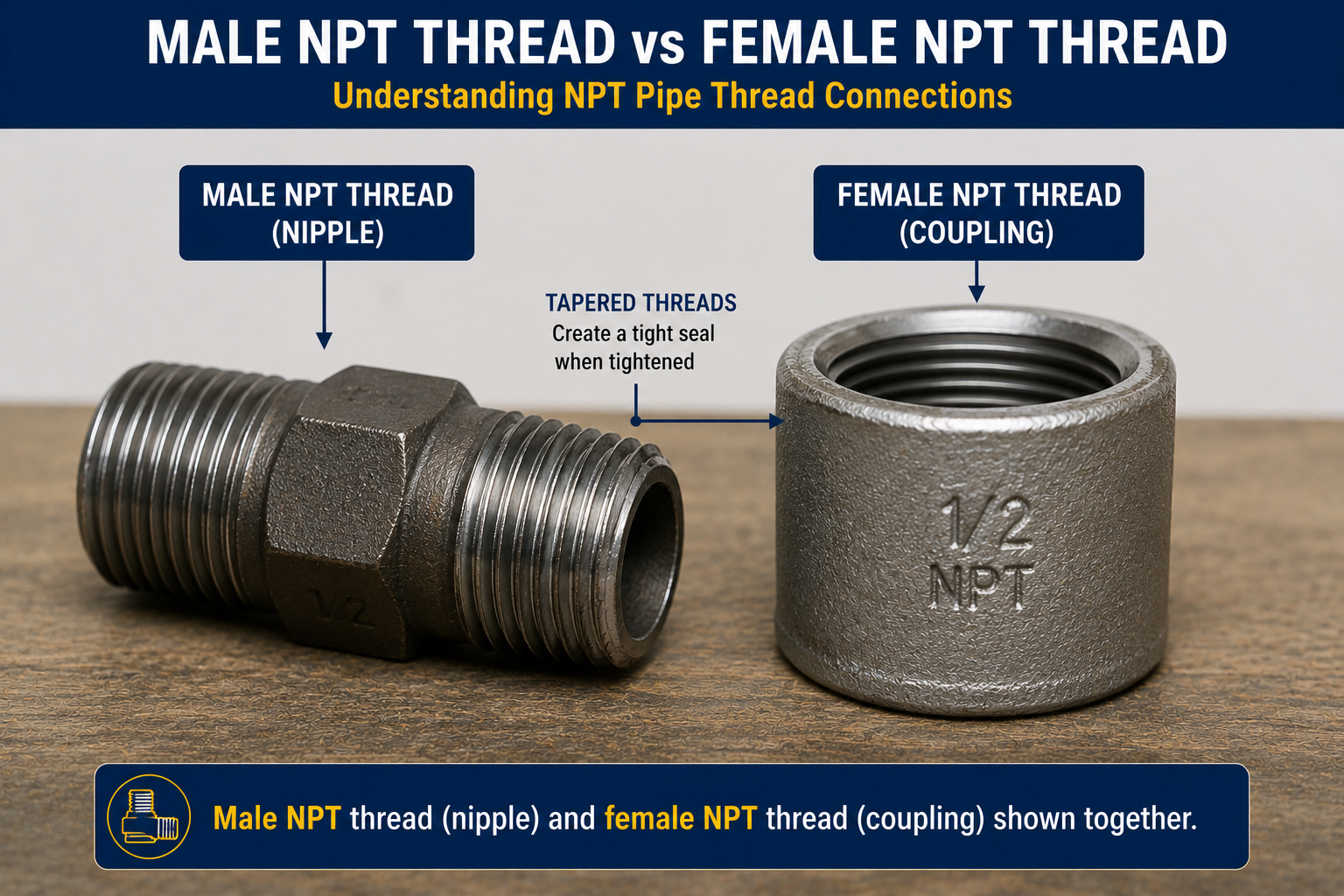
External and internal NPT threads are commonly called male and female in practice.
Male NPT (often called MPT)
The external thread, typically on a pipe end, nipple, or plug, that threads into a female fitting.
Female NPT (often called FPT)
The internal thread, typically inside a coupling, tee, or fitting body, that receives a male thread.
MPT (male pipe thread) and FPT (female pipe thread) are widely used practical abbreviations in catalogs and industry conversation, but they are not the formal designation terminology used in ASME B1.20.1 itself. Some technical references specifically caution against treating them as standardized designations; use the formal NPT nominal size designation for precise specification.
⭐⭐⭐ NPT Thread Engagement
NPT assembly involves two distinct engagement stages defined by ASME B1.20.1.
| Stage | Designation | Description |
|---|---|---|
| Hand-tight engagement | L1 | The position reached when the joint is tightened by hand without a wrench |
| Effective thread length | L2 | The length of thread with a complete, usable profile |
| Wrench makeup | L3 (additional turns beyond L1) | Further tightening applied with a wrench beyond hand-tight to achieve final assembly |
| Size | L1 Hand-Tight (in, approx.) | L2 Effective Thread (in, approx.) |
|---|---|---|
| 1/2″ | 0.320 | 0.534 |
| 3/4″ | 0.339 | 0.546 |
| 1″ | 0.400 | 0.683 |
ASME B1.20.1 provides hand-tight (L1) and wrench makeup (L3) reference dimensions, but actual required rotation beyond hand-tight depends on the specific fitting, material, thread condition, and sealant used. Do not treat a generic chart as a universal “turn X number of times” installation rule for every application.
Equipment for Your Project
Affiliate disclosure: As an Amazon Associate, ConcreteCalculate earns from qualifying purchases. We may also earn a commission from other affiliate links at no additional cost to you.
⭐⭐⭐ NPT Thread Sealing
NPT’s tapered geometry contributes to sealing, but practical sealing still depends on additional factors.
Thread interference
As NPT threads are tightened, the taper creates increasing metal-to-metal contact pressure, which is central to how the joint resists leaks.
PTFE tape
A common sealing aid wrapped around male NPT threads before assembly, filling small gaps and reducing friction/galling during installation.
Pipe thread sealant (pipe dope)
A liquid or paste compound applied to threads, sometimes preferred for certain fluids, pressures, or thread conditions where tape may not be suitable.
Application-specific requirements
The correct sealant, sealing method, and installation torque depend on the fluid, pressure, temperature, material, thread condition, and manufacturer’s specific requirements. NPT threads are designed as a sealing threaded connection, but real-world sealing practice always depends on these application-specific factors.
PTFE tape direction
Wrap tape in the same direction the fitting will be threaded in (typically clockwise when viewed from the end being threaded), so tightening does not tend to unwind the tape.
NPT thread torque
Installation torque for NPT fittings depends heavily on material, lubrication, sealant type, fitting design, thread condition, and the sealing requirement, so a single universal NPT torque chart is not technically defensible without a specific engineering basis for that exact application.
⭐⭐⭐ NPT Tap Drill Chart
NPT tapping differs fundamentally from tapping a straight UNC or metric hole because the thread itself is tapered.
| NPT Size | TPI | Common Tap Drill (in) |
|---|---|---|
| 1/8″ | 27 | R (0.339) or 11/32 |
| 1/4″ | 18 | 7/16 (0.4375) |
| 3/8″ | 18 | 37/64 (0.5781) |
| 1/2″ | 14 | 23/32 (0.7188) |
| 3/4″ | 14 | 59/64 (0.9219) |
| 1″ | 11.5 | 1-5/32 (1.1563) |
ASME B1.20.1 includes tap drill guidance in a nonmandatory appendix specifically because NPT tapping must account for the taper, not just a single hole diameter. A straight UNC or metric tap drill produces a constant diameter pilot hole; an NPT tap drill and tapping process produce a hole that the tapered tap can progressively engage as it advances, requiring correct starting diameter, alignment, and depth control.
NPT tapping depth
Required tap depth accounts for the taper, the desired effective thread engagement, hand-tight reference position, and bottom clearance, rather than a single straight thread depth calculation.
NPT tapping procedure overview
Select the correct NPT tap for the size, drill the correct starting hole, carefully align the tap to avoid introducing angular error into the taper, apply appropriate cutting fluid, cut gradually while clearing chips, then check the result against a known fitting or NPT gauge.
See the Tap Drill Chart for straight thread (UNC/UNF/metric) tap drill reference, which uses fundamentally different formulas than tapered NPT tapping.
⭐⭐⭐ NPT Pipe Thread Gages & Tolerances
Formal NPT thread verification uses dedicated gaging tools distinct from casual field identification.
L1 plug gauge
Used to verify internal (female) NPT thread dimensions against the hand-tight engagement reference position.
L1 ring gauge
Used to verify external (male) NPT thread dimensions against the same hand-tight reference position.
Working gauges
Production gauges used for routine dimensional verification, distinguished from master or reference gauges used for calibration.
GO / NOT-GO gaging
The GO condition confirms the thread is not oversized on the checked dimension, while the NOT-GO condition confirms the thread is not undersized, following the same general acceptance logic used across other formal thread gaging systems.
| Tolerance Element | What It Controls |
|---|---|
| Taper tolerance | Permitted variation in the thread’s taper rate along its length |
| Lead tolerance | Permitted variation in thread pitch/spacing |
| Thread angle tolerance | Permitted variation in the 60 degree included thread angle |
ASME B1.20.1 specifies tolerances associated with taper, lead, and thread angle for NPT and related general purpose pipe threads. Manufacturing variation within these tolerances affects final fit, engagement position, and sealing performance, which is why formal gaging exists as a distinct discipline from simple field identification.
⭐ NPT Applications
NPT is used across a wide range of fluid and pressure carrying systems.
Plumbing
Common residential and commercial sizes include 1/4, 3/8, 1/2, 3/4, and 1 inch NPT for water supply and drainage fittings.
Hydraulic equipment ⭐
Hydraulic systems can involve multiple thread standards including NPT, SAE, JIC, ORB, BSP, and metric fittings on the same piece of equipment. Never identify a hydraulic fitting by appearance alone; always measure and verify.
Pneumatic applications
Air fittings, regulators, valves, and compressors commonly use smaller NPT sizes such as 1/8, 1/4, and 3/8 inch.
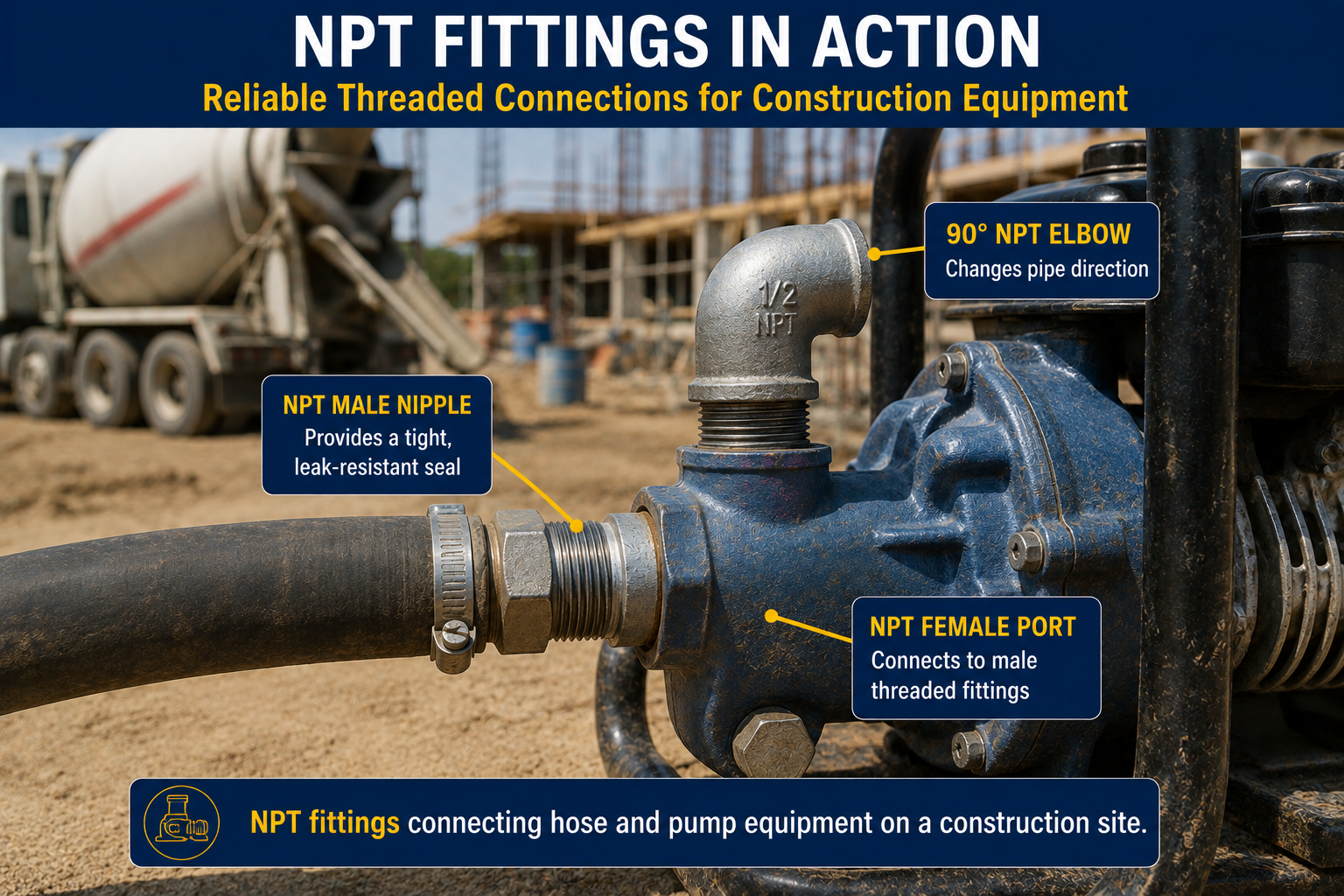
Construction equipment ⭐
Pumps, compressors, water systems, concrete equipment, and pressure equipment used on construction sites commonly rely on NPT fittings for fluid and air connections; verify size and thread type before sourcing replacement fittings.
⭐⭐⭐ NPT Thread Visual Guide
Original diagrams built specifically to explain NPT’s most confusing characteristics.
How to Choose the Correct NPT Fitting
Follow this sequence to avoid the most common NPT sourcing mistakes.
Confirm the part is actually NPT and not BSP, metric pipe thread, or a straight fastener thread.
Identify whether the existing connection is external or internal thread.
Use a caliper at the largest end of the thread.
Use a pitch gauge or count threads over one inch.
Match OD and TPI together against the standard dimension chart.
Confirm the diameter visibly decreases along the thread’s length.
Confirm the fitting material and rating suit the actual fluid, pressure, and temperature.
Choose matching NPT hardware and an appropriate sealing method for the application.
⭐ NPT Identification Worked Examples
These examples show the complete measure and compare process.
1. 1/2 NPT
2. 3/4 NPT
3. 1 NPT
4. Why 1/2 NPT Is Not 0.5 Inches
Common NPT Thread Identification Mistakes
Most NPT sourcing and installation problems trace back to one of these errors.
❌ Assuming 1/2 NPT has a 0.5 inch OD
Nominal size never equals actual measured diameter for NPT.
❌ Measuring diameter only
Some NPT sizes share close diameters; TPI is needed to confirm.
❌ Measuring TPI only
Multiple NPT sizes share identical TPI values.
❌ Confusing NPT with UNC
Tapered pipe thread versus straight fastener thread; entirely different systems.
❌ Confusing NPT with BSP
Different thread angle and crest/root form despite superficially similar sizing.
❌ Confusing NPT with metric
Different pitch conventions, geometry, and diameter systems.
❌ Confusing NPT with NPTF
NPTF has tighter dry-seal tolerances; do not assume interchangeability.
❌ Ignoring taper
Failing to check for a tapered profile can lead to a wrong thread system assumption.
❌ Using the wrong sealant
Application, fluid, and manufacturer requirements should guide sealant choice.
❌ Assuming all pipe threads are interchangeable
NPT, NPS, NPSM, BSPT, and BSPP are all distinct systems.
❌ Confusing nominal pipe size with actual OD
This is the single most common NPT misunderstanding.
❌ Treating MPT/FPT as formal standard terms
These are common industry shorthand, not ASME B1.20.1 designation terminology.
Frequently Asked Questions
📄 Download NPT Thread Chart PDF
Use the print button to create a print-ready or downloadable reference. Always confirm against the current ASME B1.20.1 standard and the specific fitting manufacturer’s documentation for critical applications.
Cite or Embed This Chart
Copy the page-wide citation to reference the complete NPT Thread Chart.