
How to Create a Concrete Material Takeoff Step by Step
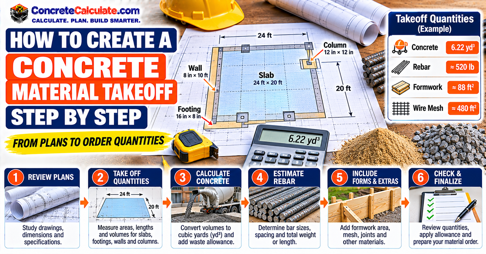
A practical, plan-driven method for measuring each concrete element, converting volumes to cubic yards, handling overlaps, taking off related materials, and checking the numbers before you order.
A concrete material takeoff is an organized, drawing-referenced list of the concrete and related materials a project needs. Measure each element from the current plans, convert its volume to cubic yards, and total the result by mix.
Show the ordering allowance as its own line. NRMCA recommends ordering about 4% to 10% more than an estimate calculated from plan dimensions, depending on job conditions.
- Confirm the current drawing set, addenda and specifications.
- Identify every concrete element and every mix class.
- Record each dimension with a drawing reference.
- Calculate cubic feet per element, then divide by 27 for cubic yards.
- Remove double-counted overlaps and apply the project’s deduction convention.
- Take off reinforcing steel, formwork, vapor retarder and accessories in their own units.
- Add the ordering allowance separately, then check the takeoff before you order.
A. Understand the process
- What Is a Concrete Material Takeoff?
- What Should Be Included in a Concrete Takeoff?
- What Drawings Do You Need Before Starting?
- Set Up a Concrete Takeoff Sheet Before Measuring
B. Review the drawings first
- Step 1: Confirm the Latest Drawing Revision
- Step 2: Read the Structural General Notes
- Step 3: Identify Every Concrete Element
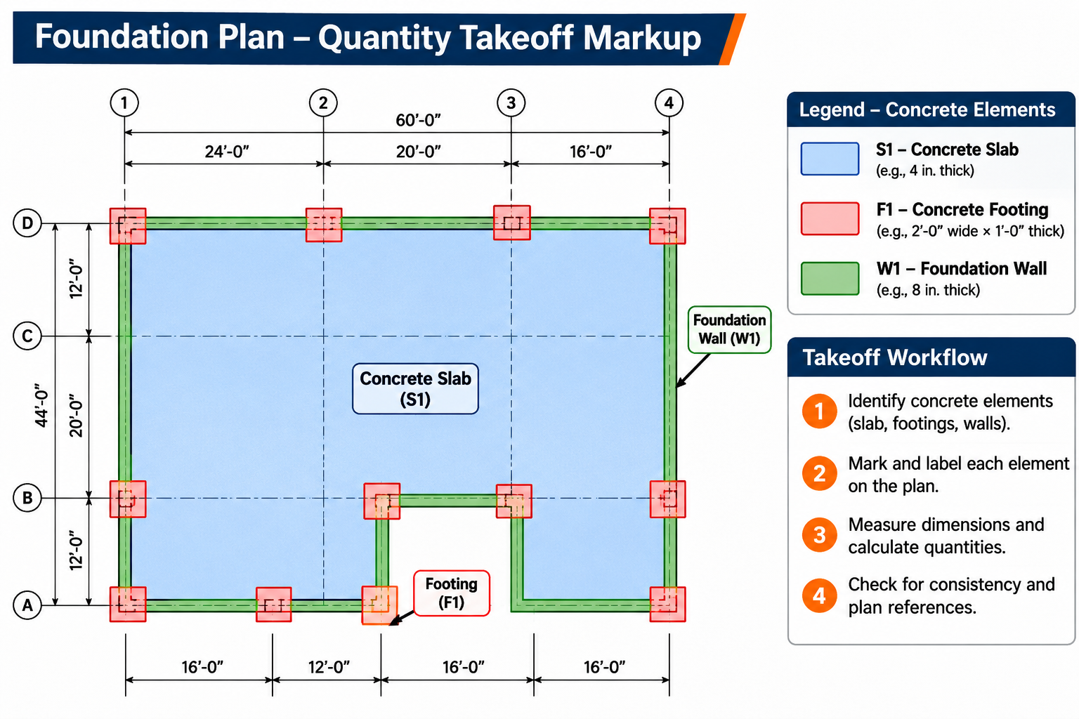
- Step 4: Mark Up the Plans by Element or Pour
C. Calculate concrete quantities
- The Basic Concrete Takeoff Formula
- How to Calculate a Concrete Slab Takeoff
- How to Calculate Strip Footings
- How to Calculate Isolated Footings and Pads
- How to Calculate Foundation and Retaining Walls
- How to Calculate Grade Beams
- How to Calculate Columns, Piers and Pedestals
- How to Calculate Concrete Stairs
- How to Handle Irregular Concrete Shapes
D. Deductions, overlaps and special cases
- Gross Volume vs. Net Concrete Volume
- How to Avoid Double-Counting Concrete at Intersections
- Slab Thickenings, Turned-Down Edges and Depressions
E. Related materials
- How to Take Off Reinforcing Steel
- How to Take Off Welded Wire Reinforcement, Fibers and Dowels
- How to Calculate Formwork Area
- Vapor Barriers, Joints, Anchors and Embedded Items
F. Ordering
G. Check and finish
What Is a Concrete Material Takeoff?
A concrete material takeoff is a structured measurement of the concrete-related materials shown on, or required by, the project documents. Its main output is concrete volume in cubic yards, with separate quantities for items such as reinforcing steel and formwork.
A takeoff is not an estimate. The takeoff produces quantities, while the estimate multiplies those quantities by unit prices and adds labor, equipment and other costs.
The Federal Highway Administration defines an estimate as the predicted project cost developed from knowledge of the costs for materials, labor and equipment. Its PS&E guidelines also say estimates should list each item with its quantity, unit and price.
That guidance was written for highway work, but the logic carries over to any concrete job. Measure first, then price.
This guide covers a plan-driven takeoff with many elements. For a quick volume on one simple slab, the how to calculate concrete guide is faster. When your quantities are ready, price them with the Concrete Project Estimator or the Contractor Bid Calculator.
What Should Be Included in a Concrete Takeoff?
The scope depends on the project. A small slab may need only ready-mix volume and a vapor retarder, while a reinforced foundation may need every item below.
- Ready-mix concrete in cubic yards, separated by mix designation
- Reinforcing steel in pounds or tons
- Welded wire reinforcement, where specified, in square feet or sheets
- Formwork in square feet of contact area
- Vapor retarder in square feet or rolls
- Joint material in linear feet
- Embeds, anchors and dowels by count
- Curing or surface treatments in square feet
- Pumping and placement items, noted for the estimate
Not every project requires every category. The drawings and specifications decide which ones apply, and each category keeps its own unit so unlike quantities are never added together.
What Drawings Do You Need Before Starting?
A reliable takeoff cannot come from a floor plan alone. FHWA describes plans as the contract drawings showing the locations, character and dimensions of the work, and specifications as the written requirements, including the method of measurement.
- Structural foundation plan and slab plan
- Sections and enlarged details
- Schedules for footings, columns, beams and reinforcement
- General notes
- Architectural plans, where dimensions must be coordinated
- Concrete specifications
- Addenda and revisions
A dimension that looks missing on the plan is often shown on a section or a standard detail. Search the whole set before assuming it does not exist.
If you are measuring an existing site instead of drawings, see how to measure concrete properly.
Set Up a Concrete Takeoff Sheet Before Measuring
Build the worksheet before you measure anything. A good sheet lets a second person trace every quantity back to the drawing without asking you what you meant.
Use these columns as your reusable framework:
- Item number and drawing or detail reference
- Concrete element and location
- Concrete class or mix
- Count, length, width and depth or thickness
- Gross volume and deductions
- Net yd³, allowance and order quantity
- Notes
The Traceability Rule
Every line should record: Drawing, element, location, dimensions, count, formula, quantity, unit. A total with no trail behind it cannot be checked, defended or corrected.
A reliable concrete takeoff remains traceable from the current drawings through quantity calculation, ordering and final delivery reconciliation.

Table 1 shows a condensed version of the sheet with two illustrative rows. These numbers are sample data, not project recommendations.
| Ref. | Element | Location | Count | L (ft) | W (ft) | D / T | Gross ft³ | Net yd³ | Allowance | Order yd³ |
|---|---|---|---|---|---|---|---|---|---|---|
| S101/A | Slab | Area A | 1 | 30 | 40 | 5 in | 500 | 18.52 | Pending | Pending |
| S201/3 | Footing F1 | Grid A/1 | 4 | 5 | 5 | 1.5 ft | 150 | 5.56 | Pending | Pending |
Table 1. Concrete takeoff worksheet template. Allowance and order columns stay pending until net quantities are final.
Step 1: Confirm the Latest Drawing Revision
Before you measure, establish which drawing set is current. Check issue dates, revision clouds, addenda, sketch revisions and any conflicts between the structural and architectural sheets.
A serious estimating error is measuring the slab from Revision 3, the footing from Revision 2 and the wall detail from the original issue. FHWA treats the plans and specifications together as the documents that define the work to be built.
Rule
Never start a final takeoff from an uncontrolled PDF set. Write the revision number and issue date on the takeoff sheet so anyone can confirm what you measured.
Step 2: Read the Structural General Notes
General notes often change a takeoff more than the plan view does. Read them fully before you record a single dimension.
- Concrete classes and specified strengths
- Slab thicknesses and footing requirements
- Reinforcement notes
- Exposure requirements
- Construction joint notes
- Special mix requirements
Do not assume the whole job uses one mixture. NRMCA notes that different mixtures are commonly used for different parts of a structure, and each mixture gets a designation that appears on the delivery ticket (NRMCA CIP 31).
That means quantities must be totaled by mix. For background on strength designations, see the Concrete PSI Guide.
Step 3: Identify Every Concrete Element
Create an element checklist before you calculate. Taking off one element at a time gives far better error checking than multiplying total building area by a guessed slab thickness.
- Slabs and slab thickenings
- Strip footings and isolated footings
- Foundation walls and retaining walls
- Grade beams
- Columns, piers and pedestals
- Equipment and housekeeping pads
- Stairs and landings
- Curbs and miscellaneous infill
Small items such as pads, curbs and stair landings are the ones most often forgotten. Work through every sheet with the checklist beside you.
Step 4: Mark Up the Plans by Element or Pour
Marking up the drawings keeps you from counting anything twice or skipping it. Two organization methods work well.
- By element type: all footings in one color, all walls in another, all slabs in a third.
- By placement or pour sequence: Footing Pour 1, Wall Pour 2, Slab Pour 3.
The second method takes more planning, but it later feeds directly into concrete ordering and truck scheduling.
The Basic Concrete Takeoff Formula
Cast-in-place concrete is estimated geometrically and sold by volume in cubic yards. One cubic yard equals 27 cubic feet (3 ft × 3 ft × 3 ft), so every dimension must be in feet before you multiply.
Formula
Variables: L is length (ft), W is width (ft), D is depth or thickness (ft), and T is thickness (in). For metric users, 1 yd³ equals about 0.7646 m³.
Check any conversion with the Concrete Cubic Yard Calculator, or look it up in the Concrete Volume Conversion Chart. Table 2 lists the geometry for each element type.
| Element | Formula (ft³) |
|---|---|
| Rectangular slab | L × W × T |
| Strip footing | Total L × W × D |
| Pad footing | Count × L × W × D |
| Wall | L × H × T |
| Grade beam | L × W × D |
| Rectangular column | L × W × H |
| Circular pier | π × r² × H |
| Irregular shape | Sum of component volumes |
Table 2. Concrete volume formulas by element. Divide each ft³ result by 27 for cubic yards.
How to Calculate a Concrete Slab Takeoff
For a rectangular slab, convert the thickness to feet, multiply, and divide by 27. Take thickness from the drawings and notes, not from habit. The Concrete Slab Thickness Chart is a general reference, but your project documents control.
Example: 30 ft × 40 ft slab, 5 in thick
Volume = 30 × 40 × (5 ÷ 12) = 500 ft³
Cubic yards = 500 ÷ 27 = 18.52 yd³
To verify a single slab quickly, use the Concrete Slab Calculator. For a general quick estimate, the Concrete Calculator also works.
How to Calculate Strip Footings
Strip footings run in continuous lines. Add up the length of each footing size separately, then multiply by its own width and depth.
- Separate footings of different sizes into different lines.
- Measure along the footing centerline so corners and intersections are not counted twice.
- Check stepped footings against the section at every elevation change.
Example: 140 ft of footing, 2 ft wide, 1 ft deep
Volume = 140 × 2 × 1 = 280 ft³
Cubic yards = 280 ÷ 27 = 10.37 yd³
For footing background, see the Concrete Footing Guide, and use the Concrete Footing Calculator to cross-check your numbers.
How to Calculate Isolated Footings and Pads
Isolated footings are counted by type, and the count multiplies the volume of a single footing.
Here N is the number of identical footings. Do not assume every footing is the same. Read the footing schedule and calculate each mark on its own line.
- F1: 4 × (5 × 5 × 1.5 ft) = 150 ft³ = 5.56 yd³
- F2: 6 × (3 × 3 × 1 ft) = 54 ft³ = 2.00 yd³
- F3: 2 × (4 × 4 × 1.25 ft) = 40 ft³ = 1.48 yd³
These sizes are illustrative, not design values. Together the three footing types total 9.04 yd³. Keeping each mark separate means one revised footing does not force you to redo the rest.
How to Calculate Foundation and Retaining Walls
Calculate each wall thickness separately. Take wall height from the sections and elevations, including any stem height above the footing.
Account for openings only when the estimating method or specification calls for it. Do not borrow a universal minimum opening size for deductions from another project.
Example: wall 40 ft long, 4 ft high, 8 in thick
Volume = 40 × 4 × (8 ÷ 12) = 106.67 ft³
Cubic yards = 106.67 ÷ 27 = 3.95 yd³
Check your result with the Concrete Wall Calculator.
How to Calculate Grade Beams
A grade beam is its cross-sectional area multiplied by its length. For a rectangular grade beam, V equals L × W × D.
Example: 24 ft long, 1.5 ft wide, 2 ft deep
Volume = 24 × 1.5 × 2 = 72 ft³
Cubic yards = 72 ÷ 27 = 2.67 yd³
Watch for overlap with footings, pile caps, columns and slabs. Decide where one element ends and the next begins before you calculate anything.
For example, count the grade beam over its clear length between footings and count each footing in full at the intersection. Apply the same boundary rule everywhere so concrete is neither omitted nor counted twice.
How to Calculate Columns, Piers and Pedestals
Use a rectangular formula for square or rectangular columns and a circular formula for round piers. Divide the cubic feet by 27 in either case.
- Rectangular column, 1.5 ft × 1.5 ft × 10 ft: 22.5 ft³, or 0.83 yd³ each
- Round pier, 2 ft diameter (r = 1 ft) × 6 ft: π × 1² × 6 = 18.85 ft³, or 0.70 yd³ each
These sizes are illustrative. Place columns of different sizes on separate lines and multiply each by its count. The Concrete Column Calculator handles both shapes.
How to Calculate Concrete Stairs
There is no safe one-size stair formula, because waist slabs, landings and support geometry vary from design to design. Choose one of two approaches.
- Section-based: take the cross-sectional area of the stair profile from the section drawing and multiply by the stair width.
- Component-based: split the stair into measurable shapes, such as the landing as a slab and the flight as a prism, then add the volumes.
Confirm landing thickness and any thickened edges from the details. The Concrete Stairs Calculator gives a useful cross-check.
How to Handle Irregular Concrete Shapes
Break irregular geometry into simple pieces, calculate each one, and add the results. Useful building blocks include:
- Rectangles: L × W × thickness
- Triangles: ½ × base × height × thickness
- Trapezoids: ½ × (a + b) × height × thickness
- Circles: π × r² × thickness
- Repeated sections: one section volume × number of repeats
For highly irregular structures, you can use design-model or CAD quantities, but only after checking the source geometry against the drawings.
Table 3 pulls the earlier elements into one small illustrative project. It assumes the footing centerlines form a 30 ft × 40 ft rectangle, which gives 140 ft of footing.
| Element | Calculation | Concrete (yd³) |
|---|---|---|
| Slab, 30 × 40 ft × 5 in | 30 × 40 × 5/12 ÷ 27 | 18.52 |
| Strip footing, 140 ft × 2 ft × 1 ft | 140 × 2 × 1 ÷ 27 | 10.37 |
| 4 pad footings, 4 × 4 × 1 ft | 4 × 4 × 4 × 1 ÷ 27 | 2.37 |
| 2 equipment pads, 4 × 6 × 0.5 ft | 2 × 4 × 6 × 0.5 ÷ 27 | 0.89 |
| Theoretical total | Sum of elements | 32.15 |
Table 3. Worked whole-project example. Illustrative small structure, net theoretical volume only.
Separate step: ordering allowance
Apply the allowance only after the net total is final. With an illustrative 5% allowance: 32.15 × 1.05 = 33.76 yd³, which is about 1.61 yd³ extra.
The 5% is an example only. NRMCA’s broader guidance is roughly 4% to 10%, depending on project conditions.
Gross Volume vs. Net Concrete Volume
Gross volume is the bounding geometry of an element. Net volume is what remains after approved deductions or adjustments, such as large openings, blockouts, voids and recesses.
The deduction question has no universal answer. Some public agency measurement methods intentionally do not deduct embedded items such as reinforcing steel or joint material, while other methods treat openings differently.
Follow the measurement provisions in your project specifications, apply one convention across the whole takeoff, and write that convention in the notes.
Do Not Invent a Deduction Rule
Do not copy an opening-size threshold from another project. Use the rule in your specification or estimating standard, and document it on the takeoff sheet.
How to Avoid Double-Counting Concrete at Intersections
Double-counting happens wherever two elements meet. Define the boundary for each pair before you calculate.
- Wall over footing: count the footing to its top, and start the wall there.
- Column into footing: measure column height from the top of the footing.
- Grade beam crossing a footing: count the intersection once, using one consistent boundary.
- Slab over a grade beam or thickening: count the slab thickness once.
- Footing corners: measure along the centerline, not the outside edge.
Example: corner overlap on a strip footing
A 2 ft wide, 1 ft deep footing follows the centerline of a 30 ft × 40 ft rectangle. The centerline length is 140 ft, so the correct volume is 140 × 2 × 1 = 280 ft³, or 10.37 yd³.
Measuring the outside edges instead (32 ft × 42 ft, perimeter 148 ft) gives 296 ft³, or 10.96 yd³. The 16 ft³ difference, about 0.59 yd³, is the four corner squares counted twice.
Slab Thickenings, Turned-Down Edges and Depressions
For integral thickenings, calculate the base slab volume plus only the additional depth. Adding the full thick section on top of the full slab counts the base thickness twice.
For integral slab thickenings, calculate only the additional depth beyond the base slab to avoid double-counting concrete.
Example: 4 in slab with a 12 in deep edge
Assume a 12 in wide turned-down edge around a 140 ft perimeter. These values are illustrative only. The extra depth is 12 minus 4, or 8 in, which is 0.667 ft.
Correct extra volume = 140 × 1 × 0.667 = 93.3 ft³, or 3.46 yd³, added to the base slab.
The wrong method adds the full 12 in section, or 140 ft³ (5.19 yd³), on top of the full slab. That overstates the quantity by about 1.73 yd³.
Depressions work the same way in reverse. Measure the reduced thickness as a subtraction from the base slab and record it as its own line.
How to Take Off Reinforcing Steel
Concrete is measured in cubic yards, but reinforcing steel is measured by weight. FHWA lists a reinforcing bar list and bar bending diagram among the items that bridge plans should include, and CRSI publishes reference data on standard bar sizes, weights and hooks.
- Identify the bar mark from the plans and schedules.
- Record the bar size and the spacing or count.
- Determine each cut length from the details.
- Add laps, hooks and bends only as shown in the approved details.
- Total the length for each bar size.
- Convert to weight using the nominal weight per foot.
Example: #4 bars
Assume 12 bars, each 20 ft long. The nominal weight of a #4 bar under ASTM A615 is 0.668 lb/ft.
Total length = 12 × 20 = 240 ft
Weight = 240 × 0.668 = 160.3 lb, or about 0.08 ton
Do not invent lap lengths from rules of thumb. Take them from the structural details or the design.
If the drawings include a bar schedule, use it to speed up the takeoff. Then reconcile it with the current drawings and revisions before ordering, because a schedule can be outdated or approximate.
Helpful tools include the Rebar Calculator, the Rebar Weight Per Foot Calculator, the Rebar Size Chart, the Rebar Spacing Chart and the Concrete Cover Chart. If you are unsure whether a slab needs steel at all, read Does Concrete Need Rebar?
How to Take Off Welded Wire Reinforcement, Fibers and Dowels
These three items are quantified differently, so keep them on separate lines.
- Welded wire reinforcement: measured in square feet or sheets and rolls, based on the specified product and its required laps.
- Fibers: usually ordered as a dosage in the concrete mixture. Do not estimate them as an area unless the supplier or project documents give a dosage.
- Dowels: counted, with each dowel’s size and length taken from the details.
The Concrete Wire Mesh Calculator can help with mesh areas and sheet counts. Take lap requirements from the specification rather than from memory.
How to Calculate Formwork Area
Formwork is measured by contact surface area, not by concrete volume. It is also treated as its own construction system, which is why ACI publishes a dedicated guide to formwork for concrete.
- Wall, both faces formed: area = 2 × L × H. A 40 ft long, 8 ft high wall gives 2 × 40 × 8 = 640 ft².
- Footing with all four sides formed: area = 2 × (L + W) × D. A 5 ft × 5 ft × 1.5 ft footing gives 2 × (5 + 5) × 1.5 = 30 ft² each.
- Slab edge form: area = perimeter × thickness. A 140 ft perimeter at 5 in gives 140 × 5/12 = 58.3 ft².
Check the sections to see which faces are actually formed. Footings may have formed sides, earth-formed faces and no bottom form.
Contact area is the measured quantity. How many times forms are reused is a separate estimating decision.
Vapor Barriers, Joints, Anchors and Embedded Items
These materials are not part of the ready-mix quantity, and they are easy to miss. Quantify each one in the unit that fits it, as shown in Table 4.
| Material | Common takeoff unit | Main source of quantity |
|---|---|---|
| Ready-mix concrete | yd³ | Plans and details |
| Reinforcing bars | lb / ton | Structural plans, bar schedules |
| Welded wire reinforcement | ft² / sheets | Slab notes |
| Formwork | ft² contact area | Geometry and construction method |
| Vapor retarder | ft² / rolls | Slab details and specifications |
| Joint material | linear ft | Joint plan and details |
| Waterstop | linear ft | Structural details |
| Anchor bolts, sleeves | each | Anchor schedule, details |
| Embedded plates, dowels | each / lb | Structural details |
| Curing compound, sealer | ft² plus product coverage | Specifications plus manufacturer data |
Table 4. Concrete-related materials and takeoff units.
For vapor retarder details, read the Concrete Vapor Barrier Guide. For joint layouts, see concrete control joints.
For curing compound, use the manufacturer’s stated coverage with the Curing Compound Calculator. Never assume any of these items is included automatically in the ready-mix price.
How Much Extra Concrete Should You Add?
Takeoff quantity is the calculated geometry from the drawings. Order quantity is that figure plus an allowance for real placement conditions. NRMCA says the quantity ordered should be 4% to 10% more than an estimate calculated from plan dimensions, to account for contingencies (NRMCA CIP 31).
That is a range, not a fixed rule. Where you land in it depends on several job conditions.
- Excavation accuracy and subgrade variability
- Form accuracy and irregular geometry
- Placement losses
- Project size
- Your ability to measure the remaining quantity during placement
Example
Net takeoff = 50.0 yd³. With a 5% ordering allowance: 50.0 × 1.05 = 52.5 yd³.
Calculate the net quantity first, then apply the allowance as its own visible step. Never fold a flat 10% into every element.
NRMCA also advises making a good estimate before ordering, re-evaluating the quantity needed to finish a placement, and avoiding excessive orders or small clean-up loads. The How Many Yards of Concrete Do I Need? guide covers the same idea for small jobs.
Convert the Takeoff Into Concrete Loads and Pour Quantities
Once the order quantity is set, divide it by the planned load size to estimate the number of loads.
NRMCA states that truck mixer capacity varies from about 8 to 12 cubic yards, so do not assume every truck carries exactly 10 yd³.
Using the 33.76 yd³ order from Table 3 and a 10 yd³ planned load gives about 3.4 loads. That could mean three full loads plus a partial load, and the supplier decides actual dispatch quantities.

The delivery ticket is your check on what arrives. NRMCA says the purchaser should verify the delivered mixture against its designation, then check and sign the ticket and note any special occurrences. See how to read a ready-mix concrete delivery ticket.
Related tools include the Ready Mix Truck Calculator and the Ready Mix Concrete Truck Load Chart. To price the order, see concrete cost per yard and concrete delivery cost.
How to Check a Concrete Takeoff for Errors
Run a structured check before you price or order. Indiana DOT’s quantity estimating chapter offers a good model: computation sheets are retained, and both the preparer and a checker sign or initial and date each one.
The same manual says not to round raw figures until they reach the quantity summary tables, and to round structural concrete to the nearest 0.1 yd³. That keeps small rounding errors from stacking up.
If the plans include a summary of quantities, compare your totals against it and investigate any difference. Table 5 lists the most common takeoff errors and how to prevent them.
| Error | Result | Prevention |
|---|---|---|
| Wrong drawing revision | Missing or incorrect quantity | Revision check first |
| Inches treated as feet | Huge volume error | Standardize units |
| Forgetting ÷ 27 | ft³ mistaken for yd³ | Formula check |
| Wall and footing intersection double-counted | Overestimate | Define element boundaries |
| Full slab thickening counted twice | Overestimate | Calculate incremental depth |
| Missing small pads or stairs | Underestimate | Element checklist |
| Different mix classes combined | Procurement error | Separate by mix designation |
| Allowance applied before net quantity is known | Hidden estimating error | Show allowance separately |
| Bar schedule trusted blindly | Rebar ordering error | Reconcile to plans |
| Truck capacity used as exact order quantity | Dispatch mismatch | Confirm loads with the supplier |
Table 5. Top concrete takeoff errors.
Every takeoff quantity should be traceable back to a specific plan, detail, dimension and location.
After the takeoff is priced and the pour is finished, compare planned and actual cost with the Construction Job Cost Variance Calculator. Then run the final checklist in Table 6 before you place the order.
| QA question | Checked? |
|---|---|
| Latest plans and addenda used? | ☐ |
| Structural notes reviewed? | ☐ |
| All concrete classes separated? | ☐ |
| Every concrete element identified? | ☐ |
| All dimensions traceable to a drawing? | ☐ |
| Inches converted correctly? | ☐ |
| Cubic feet converted to cubic yards? | ☐ |
| Intersections checked for duplicates? | ☐ |
| Openings and blockouts handled consistently? | ☐ |
| Rebar checked against schedules and details? | ☐ |
| Formwork measured separately? | ☐ |
| Accessories included? | ☐ |
| Theoretical volume separated from order allowance? | ☐ |
| Plan quantity checked where available? | ☐ |
| Final takeoff independently reviewed? | ☐ |
Table 6. Final takeoff QA checklist.
Concrete Material Takeoff FAQs
What is a concrete material takeoff?
A concrete material takeoff is a structured, drawing-referenced measurement of the concrete and related materials a project needs. It produces quantities such as cubic yards of concrete, pounds of rebar and square feet of formwork before any pricing is done.
What drawings do I need for a concrete takeoff?
You need the current structural foundation and slab plans, sections, details, schedules, general notes, concrete specifications and addenda. Architectural plans help where dimensions must be coordinated.
How do you calculate concrete cubic yards from plans?
Convert every dimension to feet, multiply length by width by depth to get cubic feet, then divide by 27. For example, a 30 ft by 40 ft slab that is 5 in thick is 30 × 40 × (5 ÷ 12) ÷ 27, or 18.52 yd³.
Should I subtract rebar volume?
Usually not. Many measurement methods do not deduct embedded reinforcement, but the rule comes from your project specification or estimating convention. Apply one convention to the whole takeoff and note it on the sheet.
How much extra concrete should I order?
NRMCA guidance says to order about 4% to 10% more than an estimate calculated from plan dimensions, to cover contingencies. The right amount depends on excavation accuracy, form accuracy, geometry, placement losses and project size.
Is 10% waste always required?
No. The 4% to 10% range is an ordering allowance based on job conditions, not a universal waste factor. Calculate the net quantity first, then add the allowance as a separate line.
How do I calculate formwork?
Measure the contact surface area that actually needs forming, not the concrete volume. A wall formed on both faces is 2 × length × height, and a footing may have formed sides, earth-formed faces and no bottom form.
How do I calculate reinforcing steel?
List each bar mark, size and count, find each cut length from the details, total the length for each size, and multiply by the nominal weight per foot. For example, 240 ft of #4 bar at 0.668 lb/ft weighs about 160.3 lb.
Should I trust the plan quantity schedule?
Use it as a cross-check, not a replacement for your own takeoff. Reconcile any schedule or bar list with the current drawings and revisions, and investigate differences before you order.
What is the difference between a takeoff and an estimate?
A takeoff measures quantities from the drawings. An estimate multiplies those quantities by unit prices and adds labor, equipment and other costs to predict project cost.
Conclusion
A good concrete takeoff is traceable from the current drawing to the delivery ticket. Measure each element, convert to cubic yards, remove overlaps, keep related materials in their own units, and show the ordering allowance as a separate line.
Start with a quick volume check, then build the full takeoff.
Open the Concrete Slab Calculator