Machine Screw Size Chart 2026 – Diameter, TPI, UNC & UNF
Machine Screw Size Chart
Diameter, TPI, UNC & UNF
Complete inch-series machine screw reference: numbered and fractional sizes, diameter, TPI, thread series, length, head style, drive type and matching hardware.
 Reviewed by Muhammad Ramzan Babar, PhD Researcher & Calculator Developer · View Profile
The Screw Size Chart covers broad screw categories and applications. This page focuses specifically on machine-threaded inch-series fasteners: nominal diameter, TPI, UNC/UNF, length, head type, drive, fit and ASME B18.6.3 dimensional context.
⭐⭐⭐ Machine Screw Size Chart: Quick Reference
UNC and UNF are shown separately. The same nominal diameter can have different thread counts and cannot use the same nut or tapped hole.
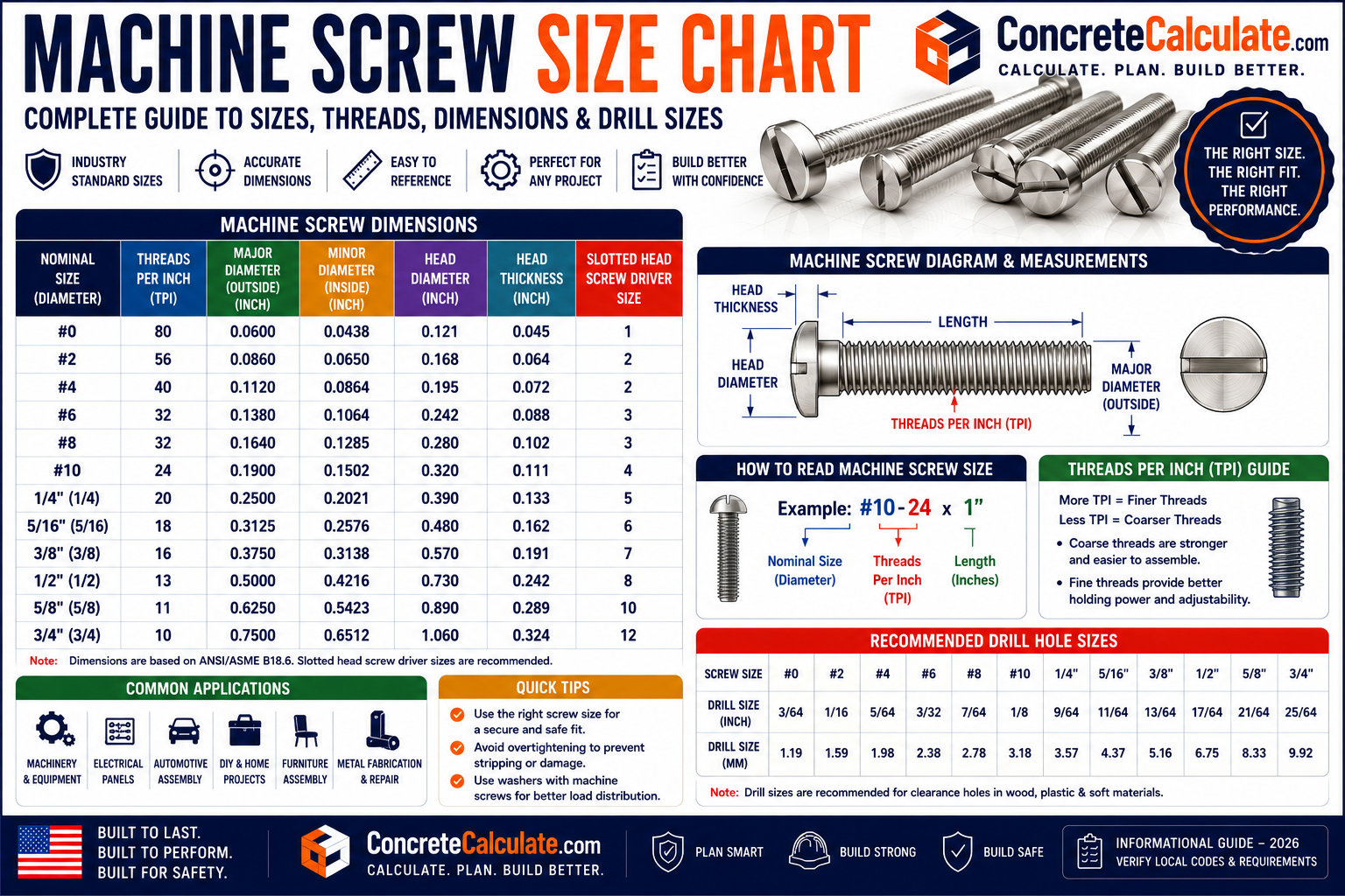
| Machine Screw Size | Major Diameter | UNC TPI | UNF TPI | Common Lengths | Common Head Styles |
|---|---|---|---|---|---|
| #0 | 0.060″ | — | 80 | 1/8″–1/2″ | Pan, flat, round |
| #1 | 0.073″ | 64 | 72 | 1/8″–3/4″ | Pan, flat, round |
| #2 | 0.086″ | 56 | 64 | 1/8″–1″ | Pan, flat, round |
| #3 | 0.099″ | 48 | 56 | 1/8″–1″ | Pan, flat, round |
| #4 | 0.112″ | 40 | 48 | 1/8″–1-1/4″ | Pan, flat, oval |
| #5 | 0.125″ | 40 | 44 | 1/8″–1-1/2″ | Pan, flat, round |
| #6 | 0.138″ | 32 | 40 | 1/8″–2″ | Pan, flat, binding |
| #8 | 0.164″ | 32 | 36 | 1/4″–2″ | Pan, flat, truss |
| #10 | 0.190″ | 24 | 32 | 1/4″–2-1/2″ | Pan, flat, hex washer |
| #12 | 0.216″ | 24 | 28 | 1/4″–3″ | Pan, flat, hex washer |
| 1/4″ | 0.250″ | 20 | 28 | 1/4″–3″+ | Pan, flat, hex |
| 5/16″ | 0.3125″ | 18 | 24 | 1/2″–3″+ | Pan, flat, hex |
| 3/8″ | 0.375″ | 16 | 24 | 1/2″–4″+ | Pan, flat, hex |
ASME B18.6.3-2024 covers complete general and dimensional data for various inch-series slotted and recessed head machine screws, tapping screws and metallic drive screws. Individual head-style, recess and thread details must be read from the applicable table within the standard or manufacturer data.
⭐⭐⭐ What Is a Machine Screw?
A machine screw is a machine-threaded fastener designed to mate with a nut or a pre-threaded hole.
Typical applications
Electronics, appliances, machinery, electrical equipment, automotive components, enclosures, sheet-metal assemblies, furniture hardware and general equipment assembly.
Machine thread design
Machine screws use standardized thread forms such as UNC or UNF and normally mate with a corresponding nut or tapped hole rather than forming their own thread.
Machine screw vs wood screw
Machine screws have uniform machine threads and are intended for metal nuts/tapped holes; wood screws have deeper, more widely spaced threads intended to grip wood fibers.
Machine screw vs tapping screw
Machine screws use a pre-existing thread; tapping screws form or cut their mating thread into material during installation.
⭐⭐⭐ Machine Screw Size Chart Explained
Reading a designation correctly gives diameter, thread count and length.
| Designation | Part | Meaning |
|---|---|---|
| #10-32 × 1″ | #10 | Nominal screw size, 0.190″ major diameter |
| 32 | 32 threads per inch (UNF for #10) | |
| 1″ | Nominal screw length, measured according to head style |
#10-24 and #10-32 share the same #10 major diameter but have different TPI and cannot use the same nut or tapped hole. The first is UNC coarse; the second is UNF fine.
⭐⭐⭐ How Machine Screw Sizes Are Measured
Machine screw identification requires more than one dimension.
Major diameter
Largest diameter across external thread crests, measured with a caliper.
Thread pitch/TPI
Threads per inch, measured using an inch thread gauge or by counting threads over a known one-inch length.
Length
Measured differently depending on whether the head is countersunk or non-countersunk.
Head and drive
Identify head style, head diameter/height where needed, and recess/drive type for correct installation and replacement.
⭐⭐⭐ Machine Screw Number Sizes
Numbered machine screws use a gauge system below 1/4 inch diameter.
| Number Size | Major Diameter (in) | Major Diameter (mm) | UNC TPI | UNF TPI |
|---|---|---|---|---|
| #0000 | 0.0210 | 0.533 | See B18.6.3 Appendix | See B18.6.3 Appendix |
| #000 | 0.0340 | 0.864 | See B18.6.3 Appendix | See B18.6.3 Appendix |
| #00 | 0.0470 | 1.194 | See B18.6.3 Appendix | See B18.6.3 Appendix |
| #0 | 0.0600 | 1.524 | — | 80 |
| #1 | 0.0730 | 1.854 | 64 | 72 |
| #2 | 0.0860 | 2.184 | 56 | 64 |
| #3 | 0.0990 | 2.515 | 48 | 56 |
| #4 | 0.1120 | 2.845 | 40 | 48 |
| #5 | 0.1250 | 3.175 | 40 | 44 |
| #6 | 0.1380 | 3.505 | 32 | 40 |
| #8 | 0.1640 | 4.166 | 32 | 36 |
| #10 | 0.1900 | 4.826 | 24 | 32 |
| #12 | 0.2160 | 5.486 | 24 | 28 |
| #14 | 0.2420 | 6.147 | 20 | 26 |
For numbered screws #0 and larger, the basic major diameter follows: major diameter (in) = screw number × 0.013 + 0.060. This applies to the nominal size system, while actual thread class/tolerance controls acceptable manufactured dimensions.
⭐⭐⭐ Machine Screw Diameter and Thread Chart
Thread series must be explicitly identified with TPI.
| Screw Size | Nominal/Major Diameter | UNC Designation | UNF Designation |
|---|---|---|---|
| #2 | 0.0860″ | #2-56 UNC | #2-64 UNF |
| #4 | 0.1120″ | #4-40 UNC | #4-48 UNF |
| #6 | 0.1380″ | #6-32 UNC | #6-40 UNF |
| #8 | 0.1640″ | #8-32 UNC | #8-36 UNF |
| #10 | 0.1900″ | #10-24 UNC | #10-32 UNF |
| #12 | 0.2160″ | #12-24 UNC | #12-28 UNF |
| 1/4″ | 0.2500″ | 1/4-20 UNC | 1/4-28 UNF |
| 5/16″ | 0.3125″ | 5/16-18 UNC | 5/16-24 UNF |
| 3/8″ | 0.3750″ | 3/8-16 UNC | 3/8-24 UNF |
See the Thread Size Chart, Thread Pitch Chart, UNC Thread Chart and UNF Thread Chart for full thread-system references.
⭐⭐⭐ UNC vs UNF Machine Screws
Same diameter, different pitch, different mating hardware.
| Feature | UNC | UNF |
|---|---|---|
| Thread | Coarse | Fine |
| TPI | Lower | Higher |
| Pitch | Larger | Smaller |
| Common use | General fastening, softer materials | Applications needing finer thread spacing or adjustment |
| #10 example | #10-24 | #10-32 |
#8-32 and #8-36 are both #8 screws, but their different thread counts mean they require different nuts or tapped holes. Matching nominal diameter without matching TPI can damage both parts.
⭐⭐⭐ Machine Screw TPI and Thread Pitch
For inch threads, pitch is the inverse of TPI.
Pitch (in) = 1 ÷ TPI. For a 32 TPI screw: 1 ÷ 32 = 0.03125 inches of pitch, approximately 0.794 mm.
| Screw Size | UNC TPI | UNF TPI | UNF Pitch (mm) |
|---|---|---|---|
| #2 | 56 | 64 | 0.397 |
| #4 | 40 | 48 | 0.529 |
| #6 | 32 | 40 | 0.635 |
| #8 | 32 | 36 | 0.706 |
| #10 | 24 | 32 | 0.794 |
| #12 | 24 | 28 | 0.907 |
⭐⭐⭐ Machine Screw Length Chart and Measurement
Length is head-style dependent, which prevents common ordering mistakes.
| Head Type | Length Measurement Method |
|---|---|
| Flat / countersunk head | Measured from the theoretical intersection of the top head surface and head diameter to the tip; commonly treated as top of head to tip for practical ordering |
| Oval countersunk head | Overall length commonly measured from tip to top of the raised head crown |
| Pan / round / binding / hex / hex washer | Measured from under the bearing surface of the head to the tip |
Machine screws can be made to many lengths, but are commonly sold in fractional increments: 1/16 inch increments up to 5/8 inch long, 1/8 inch increments above 5/8 through 1-1/2 inch, and 1/4 inch increments above 1-1/2 inch, as summarized in B18.6.3 general requirements.
⭐⭐⭐ Machine Screw Head Types
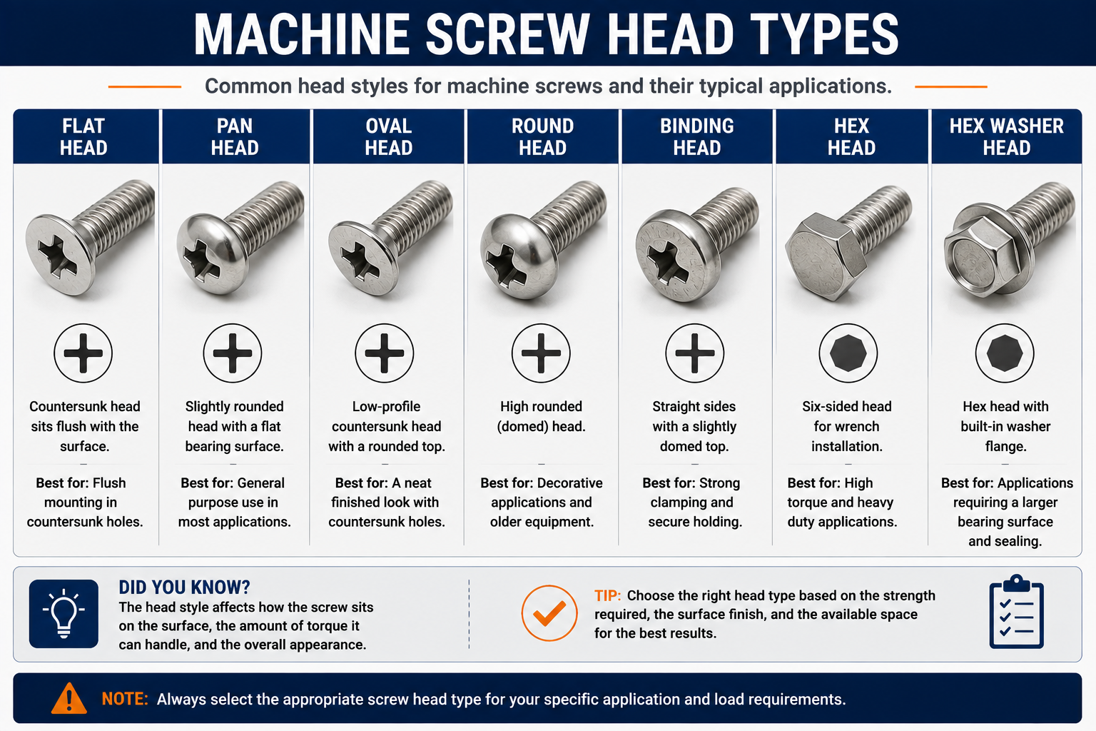
ASME B18.6.3 covers numerous head configurations, so “machine screw” does not mean one universal head shape.
Flat head
Countersunk design for flush seating. Length measurement includes the countersunk head geometry.
Oval head
Raised countersunk profile, combining a decorative rounded crown with countersunk seating.
Pan head
Rounded top, flat bearing underside, common in general assembly and enclosures.
Round head
Rounded head profile, available in slotted and recessed forms under the machine screw dimensional standard.
Truss head
Wide, low-profile head providing a larger bearing surface for thin materials.
Binding head
Head configuration with a relatively broad bearing profile, used in specific electrical and assembly applications.
Hex head
Wrench-driven head with across-flats and head-height dimensions, useful where higher installation torque or wrench access is needed.
Hex washer head
Hex head with integrated washer-like bearing surface. ASME B18.6.3 includes dedicated dimensional tables for this configuration.
Head diameter, head height, recess geometry and bearing surface differ by head style. Do not assume every #10 machine screw has the same head dimensions; consult the relevant B18.6.3 head-style table or manufacturer specification.
⭐⭐⭐ Machine Screw Drive Types
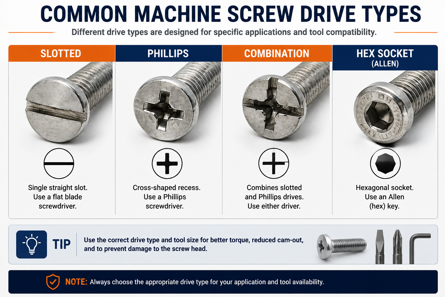
Correct drive selection protects the screw recess and improves installation reliability.
Slotted
Traditional single straight slot; requires proper blade width and depth to avoid cam-out or damage.
Phillips
Cross recess, common in commercial machine screws; use the correct driver size to avoid damaging the recess.
Combination drive
Often slotted/Phillips, allowing more than one driver option; common in commercial machine screw listings.
Hex socket
Internal hex recess used for higher torque applications; some cap screw products fall under different ASME standard families rather than B18.6.3 machine screw tables.
⭐⭐⭐ Major, Minor and Pitch Diameter
Thread diameter terminology matters for identification, fit and engineering analysis.
| Dimension | Meaning |
|---|---|
| Nominal / major diameter | Largest external thread diameter measured at the crests; corresponds to screw size designation |
| Minor diameter | Root diameter of external thread, smaller than major diameter |
| Pitch diameter | Imaginary diameter where thread width and groove width are equal; important for thread fit and inspection |
Major, minor and pitch diameter describe the threaded shank. Head diameter, head height, drive and bearing surface are separate dimensions determined by the selected head style.
⭐⭐⭐ Machine Screw Thread Classes
Thread class controls fit and tolerance, separate from size and TPI.
| Class | Thread Type | General Fit |
|---|---|---|
| 1A / 1B | External / Internal | Loosest general fit |
| 2A / 2B | External / Internal | Standard general-purpose fit |
| 3A / 3B | External / Internal | Closest precision fit |
Class 2A is the standard general-purpose external thread class used for many machine screws. Class 3A has tighter tolerance and no allowance, used when a closer precision fit is required. Thread class affects fit/tolerance, not the material strength or grade of the screw.
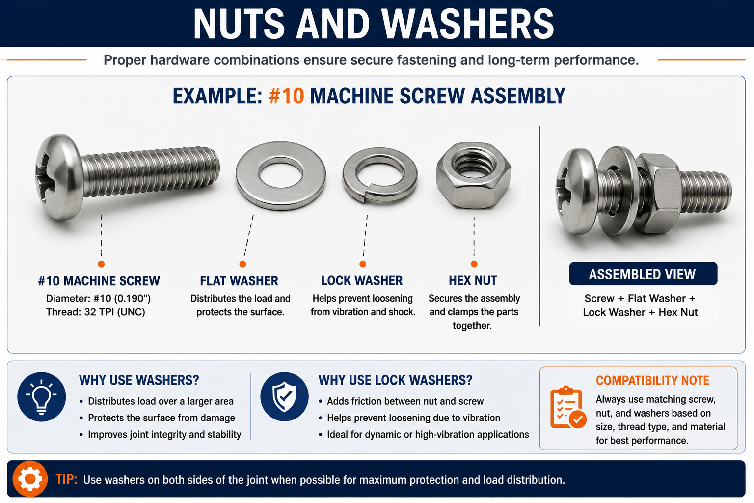
⭐⭐⭐ Machine Screw Nuts, Washers and Matching Sizes
Matching requires diameter and thread series/TPI together.
| Screw | Thread | Matching Nut |
|---|---|---|
| #4 | #4-40 UNC | #4-40 nut |
| #6 | #6-32 UNC | #6-32 nut |
| #8 | #8-32 UNC | #8-32 nut |
| #10 | #10-24 UNC | #10-24 nut |
| #10 | #10-32 UNF | #10-32 nut |
| #12 | #12-24 UNC | #12-24 nut |
| 1/4″ | 1/4-20 UNC | 1/4-20 nut |
Washer selection
Flat washers, internal/external tooth lock washers and fender-style washers have different OD, ID and thickness dimensions. Do not assume every washer with a matching nominal screw size has identical geometry.
Thread engagement
Required engagement depends on material strength, screw strength, tapped-hole depth and stripping considerations. Do not apply one universal engagement rule for all materials.
⭐⭐⭐ Machine Screw Materials, Finish and Strength
Material and finish affect corrosion resistance, strength, appearance and application suitability.
Steel machine screws
Common carbon steel and plated steel products; strength depends on the actual material/heat treatment specification, not size alone.
Stainless steel machine screws
Common grades include 18-8, 304 and 316, selected for corrosion resistance and application conditions; stainless may have different galling and torque considerations than carbon steel.
Brass machine screws
Used for corrosion resistance, electrical applications and decorative hardware; generally lower strength than many steel products.
Aluminum and specialty materials
Selected for low weight, corrosion resistance or specific compatibility requirements; always check material-specific strength and corrosion behavior.
| Finish/Coating | General Purpose |
|---|---|
| Zinc plating | General corrosion protection for indoor/mild exposure |
| Black oxide | Appearance and limited corrosion protection, typically needing oil for improved resistance |
| Nickel plating | Decorative finish and corrosion resistance in selected applications |
| Stainless finish | Material-based corrosion resistance rather than plated carbon steel |
Machine screw material or strength specification is not automatically equivalent to SAE bolt grades such as Grade 5 or Grade 8. Do not apply bolt-grade terminology or generic bolt torque tables to machine screws without confirming the actual product specification.
⭐⭐⭐ Machine Screw Comparisons
Understanding the product category prevents wrong fastener selection.
| Feature | Machine Screw | Bolt | Tapping Screw | Wood Screw |
|---|---|---|---|---|
| Typical use | Machine/equipment assembly | Structural/general fastening | Forms/cuts thread in material | Wood fastening |
| Thread mating | Nut or tapped hole | Usually nut or tapped hole | Creates mating thread | Grips wood fibers |
| Typical size range | Often smaller | Often larger | Varies by product | Varies by product |
| Standardization | ASME B18.6.3 inch series | Many bolt standards | Separate B18.6.3 provisions | Product/application-specific |
Socket head cap screws are generally covered by a different ASME standard family from basic machine screws. Do not combine cap screw head dimensions with B18.6.3 machine screw head dimensions in one ambiguous chart.
⭐⭐⭐ Metric vs Imperial Machine Screws
Inch-series machine screws and metric screws use separate dimensional and thread systems.
| Feature | Imperial Machine Screw | Metric Machine Screw |
|---|---|---|
| Diameter designation | Number size or fraction | M designation in mm |
| Pitch | TPI | mm per thread |
| Examples | #10-32, 1/4-20 | M3 x 0.5, M4 x 0.7, M6 x 1.0 |
| Thread standards | ASME Unified thread system | ISO metric thread system |
| Metric Size | Nominal Diameter | Standard Pitch | Common Lengths |
|---|---|---|---|
| M2 | 2 mm | 0.4 mm | 3–20 mm |
| M2.5 | 2.5 mm | 0.45 mm | 4–25 mm |
| M3 | 3 mm | 0.5 mm | 4–30 mm |
| M4 | 4 mm | 0.7 mm | 5–40 mm |
| M5 | 5 mm | 0.8 mm | 6–50 mm |
| M6 | 6 mm | 1.0 mm | 8–60 mm |
| M8 | 8 mm | 1.25 mm | 10–80 mm |
Converting a #8 diameter to millimeters does not make it interchangeable with an M4 screw. Diameter, pitch, thread form and tolerance must all match. See the Metric Thread Chart.
⭐⭐⭐ Machine Screw Identification and Measurement
Use a methodical sequence to identify an unknown machine screw.
Use a caliper across the external thread crests to determine major diameter and candidate number/fractional size.
Use an inch thread gauge to identify TPI, then determine whether the thread is UNC or UNF.
Use the correct head-dependent measurement method.
Determine flat, oval, pan, round, binding, hex or other head configuration.
Determine slotted, Phillips, combination, hex socket or other drive.
Identify steel, stainless, brass or other material; note plating or coating.
Match diameter and TPI together; do not force mismatched hardware.
See the Thread Identification Chart for the full thread identification workflow.
⭐⭐⭐ Machine Screw Tap Drill vs Clearance Hole
These hole types have completely different purposes.
| Hole Type | Purpose |
|---|---|
| Tap drill | Creates the pilot hole before tapping an internal thread |
| Threaded hole | Receives machine screw threads directly after tapping |
| Close clearance hole | Allows screw to pass through with minimal side play |
| Normal clearance hole | Allows standard assembly clearance |
| Loose clearance hole | Allows greater alignment tolerance or movement |
A machine screw used in a tapped hole requires the correct tap drill size for its exact diameter, TPI, desired engagement and tap type. #10-24 and #10-32 need different tap drills because their pitch differs. See the Tap Drill Chart.
Thread engagement
Thread engagement and tapped-hole depth depend on material strength, screw strength and stripping considerations; do not use one universal engagement length.
Countersink and counterbore
Flat heads use countersinks for flush seating; counterbores recess non-countersunk heads below a surface. Size must match the actual head style and manufacturer dimensions.
⭐⭐⭐ Machine Screw Applications and Torque
Machine screw torque must be determined from the actual product and joint, not the size chart alone.
Common applications
Electronics, appliances, machinery, electrical equipment, automotive components, sheet-metal assemblies, enclosures, furniture/hardware and general equipment assembly.
Torque considerations
Torque depends on material, lubrication, coating, thread condition, strength, head/drive type, preload requirement and application. Do not automatically apply generic bolt torque values to every machine screw.
Head clearance
Allow sufficient clearance around the head for driver, wrench or tool access; a screw can be dimensionally correct yet impractical to install if tooling cannot reach the head.
Strength
Machine screw strength depends on material, diameter, thread geometry and actual product specification. Dimensional standards do not automatically establish structural fastener strength.
See the Bolt Torque Chart for torque/preload principles and the Bolt Grade Chart for bolt-grade distinctions.
⭐⭐⭐ ASME B18.6.3 Machine Screw Standard
The primary inch-series machine screw dimensional standard.
Scope
ASME B18.6.3-2024 covers complete general and dimensional data for various slotted and recessed head machine screws, tapping screws and metallic drive screws recognized as American National Standard.
Dimensional coverage
The standard includes head configurations such as binding, hex, hex washer, round and round washer heads, along with many other head/recess configurations, thread dimensions, length requirements and gaging appendices.
Thread standard vs fastener standard
B18.6.3 defines product dimensions and requirements. The underlying Unified inch thread form, series, tolerance and class requirements come from separate ASME B1 thread standards such as ASME B1.1.
Length and threading
Machine screw thread length requirements depend on nominal screw size and length. B18.6.3 specifies that shorter screws generally have full-form threads extending close to the head bearing surface.
ASME currently identifies B18.6.3-2024 as the active inch-series Machine Screws, Tapping Screws, and Metallic Drive Screws standard. Cite the edition/source used whenever publishing detailed machine screw dimensions.
⭐⭐⭐ Machine Screw Visual Guide
Original diagrams explaining anatomy, designation, head measurement and thread series.
⭐⭐⭐ Machine Screw Size Worked Examples
Examples show how to decode, identify and match common machine screws.
1. Identify #8-32 × 1″
2. Identify #10-32 × 1″
3. Identify 1/4-20 × 1-1/2″
4. Metric M6 Machine Screw
⭐⭐⭐ Common Machine Screw Sizing Mistakes
Most ordering and assembly errors trace back to one of these assumptions.
❌ Confusing #8 with 8 mm
#8 is an inch-series nominal size with 0.164 inch diameter, not an 8 mm metric screw.
❌ Confusing UNC and UNF
Same diameter can have different TPI and incompatible mating hardware.
❌ Measuring head diameter as thread diameter
Measure major thread diameter across crests, not the head.
❌ Measuring flat-head length incorrectly
Countersunk head length includes the head geometry, unlike pan/round/hex styles.
❌ Matching a nut by diameter only
Nut must match diameter and TPI together.
❌ Confusing machine screws with tapping screws
Machine screws need a nut or pre-threaded hole; tapping screws form/cut their mating thread.
❌ Using metric nuts on inch screws
Similar diameter does not establish thread compatibility.
❌ Using the wrong driver
Mismatch can damage the recess and compromise installation.
❌ Assuming all heads have identical dimensions
Head dimensions depend on the selected head style and standard table.
❌ Using bolt-grade terminology incorrectly
Machine screw material/specification is not automatically SAE Grade 5 or Grade 8.
❌ Treating inch-to-mm conversion as thread equivalency
Dimensional conversion does not make metric and inch threads interchangeable.
Machine Screw Size FAQs
📄 Download Machine Screw Size Chart PDF
This PDF is a complete inch-series fastener field reference, preserving the thread series and source/standard basis for every dimensional lookup.
Cite or Embed This Chart
Copy the page-wide citation to reference the complete Machine Screw Size Chart.