Rebar Area Chart: Cross Sectional Area by Bar Size & Spacing
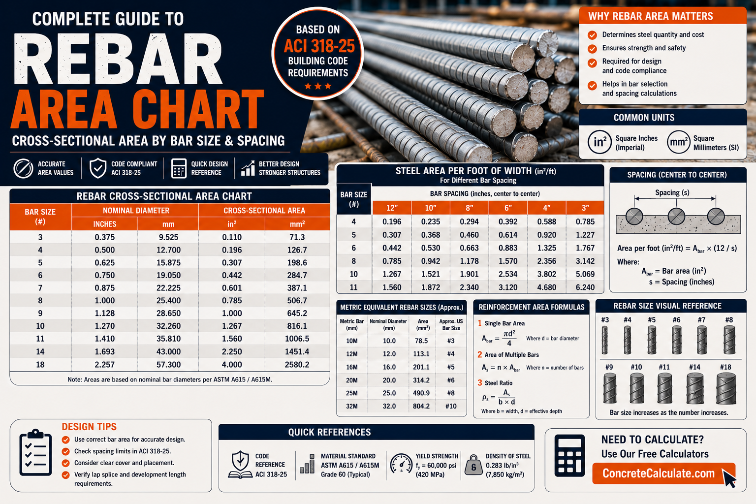
Rebar Area Chart
Cross-Sectional Area by Bar Size & Spacing
The complete rebar area reference: cross-sectional area for #3 through #18 bars in square inches and mm2, metric equivalents, and area per foot by spacing.
 Reviewed by Muhammad Ramzan Babar, PhD Researcher (Plasma Physics) & Calculator Developer, View Profile
Bar area is a reference value, not a structural design result
This chart provides standard nominal cross-sectional areas and area-per-spacing calculations. It does not determine required reinforcement area, bar size, or spacing for any project. Structural design requires evaluating loads, spans, concrete strength, and the applicable ACI CODE-318-25 provisions.
Rebar Area Chart, Quick Reference
This table shows standard nominal cross-sectional area for common U.S. bar sizes. The primary relationship this page covers is bar size to area, then area to reinforcement quantity per unit width.
| Bar Size | Metric Designation | Nominal Diameter (in.) | Area (in.2) | Area (mm2) | Weight (lb/ft) |
|---|---|---|---|---|---|
| #3 | #10 | 0.375 | 0.11 | 71 | 0.376 |
| #4 | #13 | 0.500 | 0.20 | 129 | 0.668 |
| #5 | #16 | 0.625 | 0.31 | 200 | 1.043 |
| #6 | #19 | 0.750 | 0.44 | 284 | 1.502 |
| #7 | #22 | 0.875 | 0.60 | 387 | 2.044 |
| #8 | #25 | 1.000 | 0.79 | 509 | 2.670 |
| #9 | #29 | 1.128 | 1.00 | 645 | 3.400 |
| #10 | #32 | 1.270 | 1.27 | 819 | 4.303 |
| #11 | #36 | 1.410 | 1.56 | 1006 | 5.313 |
| #14 | #43 | 1.693 | 2.25 | 1452 | 7.650 |
| #18 | #57 | 2.257 | 4.00 | 2581 | 13.600 |
Values sourced from ASTM A615/A615M standard bar sizes and CRSI reference dimensional data. Weight column shown for reference only; see the Rebar Weight Chart for complete weight data and the Rebar Size Chart for full dimensional identification.
What Is Rebar Area?
Rebar area is the cross-sectional area of one reinforcing bar, used in structural design to calculate reinforcement ratios, capacity, and steel quantity per unit width, rather than relying on bar diameter alone.
- Ab = cross-sectional area of one bar
- d = nominal bar diameter
Structural design uses steel area rather than diameter because area, not diameter, directly determines the amount of steel resisting tension or compression at a given cross-section. Published standard bar areas should be used for construction and specification purposes rather than assuming every manufactured bar is a perfect geometric cylinder; deformed bars have ribs and surface patterns that a pure geometric calculation does not capture precisely.
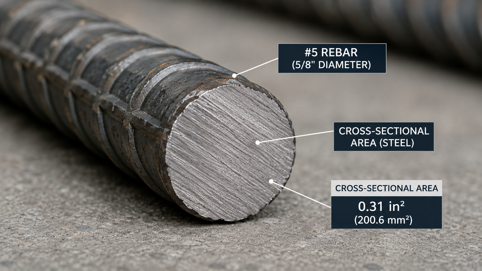
Rebar Area vs Rebar Diameter
Area increases with the square of diameter, so doubling the diameter does not double the area. This nonlinear relationship is one of the most important concepts on this page.
| Bar Size | Diameter (in.) | Area (in.2) | Diameter vs #3 | Area vs #3 |
|---|---|---|---|---|
| #3 | 0.375 | 0.11 | 1.0x | 1.0x |
| #6 | 0.750 | 0.44 | 2.0x | 4.0x |
| #9 | 1.128 | 1.00 | 3.0x | 9.1x |
Why this matters for bar substitution
A #6 bar has twice the diameter of a #3 bar but four times the area. A #9 bar has three times the diameter of a #3 bar but about nine times the area. Bar substitution decisions must account for this squared relationship rather than assuming area scales the same way diameter does.
US Rebar Area Chart, Inch-Pound Bar Sizes
ASTM A615/A615M and CRSI reference material define standard inch-pound bar sizes through #18, including the less common #14 and #18 heavy sizes.
| Bar Size | Diameter (in.) | Area (in.2) |
|---|---|---|
| #3 | 0.375 | 0.11 |
| #4 | 0.500 | 0.20 |
| #5 | 0.625 | 0.31 |
| #6 | 0.750 | 0.44 |
| #7 | 0.875 | 0.60 |
| #8 | 1.000 | 0.79 |
| #9 | 1.128 | 1.00 |
| #10 | 1.270 | 1.27 |
| #11 | 1.410 | 1.56 |
| #14 | 1.693 | 2.25 |
| #18 | 2.257 | 4.00 |
#3 through #8 bars correspond approximately to their diameter in eighths of an inch. #9, #10, and #11 bars transition to areas based on equivalent square bar sizing rather than exact eighths. #14 and #18 are heavy bars used in heavily loaded columns and specialized structural members.
Rebar Area in Square Inches
A dedicated quick-reference table isolating diameter and area in inch-pound units for fast lookup.
| Bar Size | Nominal Diameter (in.) | Area (in.2) |
|---|---|---|
| #3 | 0.375 | 0.11 |
| #4 | 0.500 | 0.20 |
| #5 | 0.625 | 0.31 |
| #6 | 0.750 | 0.44 |
| #7 | 0.875 | 0.60 |
| #8 | 1.000 | 0.79 |
| #9 | 1.128 | 1.00 |
| #10 | 1.270 | 1.27 |
| #11 | 1.410 | 1.56 |
| #14 | 1.693 | 2.25 |
| #18 | 2.257 | 4.00 |
Rebar Area in Square Millimeters
SI equivalent values. ASTM treats inch-pound and SI designations as separate standards; these are not exact geometric duplicates of the inch-pound values.
| Bar Size (Metric) | Nominal Diameter (mm) | Area (mm2) |
|---|---|---|
| #3 (#10) | 9.5 | 71 |
| #4 (#13) | 12.7 | 129 |
| #5 (#16) | 15.9 | 200 |
| #6 (#19) | 19.1 | 284 |
| #7 (#22) | 22.2 | 387 |
| #8 (#25) | 25.4 | 509 |
| #9 (#29) | 28.7 | 645 |
| #10 (#32) | 32.3 | 819 |
| #11 (#36) | 35.8 | 1006 |
| #14 (#43) | 43.0 | 1452 |
| #18 (#57) | 57.3 | 2581 |
ASTM A615/A615M explicitly treats inch-pound and SI values as separate standard units; values in each system are not necessarily exact geometric equivalents of the other and should not be mixed when checking conformance.
US Rebar Sizes and Metric Equivalents
Soft-metric designations rename the same U.S. bars using approximate millimeter diameters; they are not separate, independently sized bars.
| US Bar Size | Metric Designation | Nominal Diameter | Nominal Area |
|---|---|---|---|
| #3 | #10 | 9.5 mm | 71 mm2 |
| #4 | #13 | 12.7 mm | 129 mm2 |
| #5 | #16 | 15.9 mm | 200 mm2 |
| #6 | #19 | 19.1 mm | 284 mm2 |
| #8 | #25 | 25.4 mm | 509 mm2 |
Equivalent does not mean identical
The metric designation is a soft conversion of the same standard bar, rounded to a convenient metric number, not a separately manufactured or separately standardized bar. Do not mix U.S. and metric designations carelessly when specifying reinforcement, since a drawing calling out “#5” versus “#16” should refer to the same physical bar under ASTM A615/A615M.
Rebar Area by Bar Size
One comprehensive table covering diameter, area, metric equivalent, and typical structural context for common U.S. bar sizes.
| Bar Size | Diameter (in.) | Area (in.2) | Metric Equivalent | Typical Structural Context |
|---|---|---|---|---|
| #3 | 0.375 | 0.11 | #10 | Temperature/shrinkage steel, light slabs |
| #4 | 0.500 | 0.20 | #13 | Slabs-on-grade, sidewalks, light footings |
| #5 | 0.625 | 0.31 | #16 | Slabs, footings, light structural members |
| #6 | 0.750 | 0.44 | #19 | Beams, columns, structural slabs |
| #7 | 0.875 | 0.60 | #22 | Beams, columns, heavier footings |
| #8 | 1.000 | 0.79 | #25 | Beams, columns, foundation walls |
| #9 | 1.128 | 1.00 | #29 | Heavy beams and columns |
| #10 | 1.270 | 1.27 | #32 | Heavy columns, transfer members |
| #11 | 1.410 | 1.56 | #36 | Heavy columns, high-rise structural members |
| #14 | 1.693 | 2.25 | #43 | Heavily loaded columns, specialized structural members |
| #18 | 2.257 | 4.00 | #57 | Very heavily loaded columns, bridge piers |
For full dimensional identification including bar markings and weight, see the Rebar Size Chart rather than duplicating that data here.
Rebar Area Formula and Calculation
The geometric formula explains where nominal areas come from, but published standard areas should be used for actual construction and specification purposes.
- A = cross-sectional area
- d = diameter (consistent units, inches or mm)
- Convert in. to mm by multiplying by 25.4; convert in.2 to mm2 by multiplying by 645.16
Example: Geometric Calculation for a #6 Bar
Nominal Rebar Area vs Calculated Geometric Area
The standard area published for a bar size is based on its nominal dimensions, not a direct measurement of the deformed bar’s irregular surface profile.
| Bar Size | Published Nominal Area (in.2) | Geometric Calculation (in.2) |
|---|---|---|
| #4 | 0.20 | 0.196 |
| #5 | 0.31 | 0.307 |
| #7 | 0.60 | 0.601 |
| #8 | 0.79 | 0.785 |
ASTM A615/A615M states that nominal dimensions of a deformed bar correspond to those of a plain round bar having the same weight per unit length as the deformed bar. This is why published nominal areas closely but not exactly match a pure geometric circle calculation from the nominal diameter, and why construction and design work should always reference the published standard area rather than recalculating from scratch.
Rebar Area per Foot of Width
This formula bridges bar size and spacing into a single practical reinforcement quantity used throughout slab and wall design.
- As = steel area per foot of width (in.2/ft)
- Ab = area of one bar (in.2)
- s = center to center spacing (in.)
This calculation answers a question the bar size chart alone cannot: how much steel area actually exists across a one-foot strip of slab or wall at a given spacing. See the Rebar Spacing Chart for the spacing rules that determine which values of s are appropriate.
Rebar Area per Meter of Width
The SI equivalent calculation, bridging U.S. and metric reinforcement quantity work.
- As = steel area per meter of width (mm2/m)
- Ab = area of one bar (mm2)
- s = center to center spacing (mm)
Rebar Area by Spacing
Each cell in this table represents the steel area per foot of width for a given bar size and center to center spacing, calculated using As = Ab times 12 divided by spacing.
| Bar Size | 6 in. | 8 in. | 10 in. | 12 in. | 16 in. | 18 in. |
|---|---|---|---|---|---|---|
| #3 | 0.220 | 0.165 | 0.132 | 0.110 | 0.083 | 0.073 |
| #4 | 0.400 | 0.300 | 0.240 | 0.200 | 0.150 | 0.133 |
| #5 | 0.620 | 0.465 | 0.372 | 0.310 | 0.232 | 0.207 |
| #6 | 0.880 | 0.660 | 0.528 | 0.440 | 0.330 | 0.293 |
| #7 | 1.200 | 0.900 | 0.720 | 0.600 | 0.450 | 0.400 |
| #8 | 1.580 | 1.185 | 0.948 | 0.790 | 0.593 | 0.527 |
All values in square inches per foot of width. This table does not determine required reinforcement for any project; verify design requirements against project specifications and the applicable ACI CODE-318-25 provisions.
Rebar Area per Foot Chart
Extended reference for #9 through #11 bars at common spacings, useful for heavier structural members.
| Bar Size | 6 in. | 8 in. | 10 in. | 12 in. | 16 in. | 18 in. |
|---|---|---|---|---|---|---|
| #9 | 2.000 | 1.500 | 1.200 | 1.000 | 0.750 | 0.667 |
| #10 | 2.540 | 1.905 | 1.524 | 1.270 | 0.953 | 0.847 |
| #11 | 3.120 | 2.340 | 1.872 | 1.560 | 1.170 | 1.040 |
This reference is useful for slab reinforcement, wall reinforcement, temperature/shrinkage reinforcement, and preliminary layout comparisons, but it does not determine the required reinforcement for a specific project.
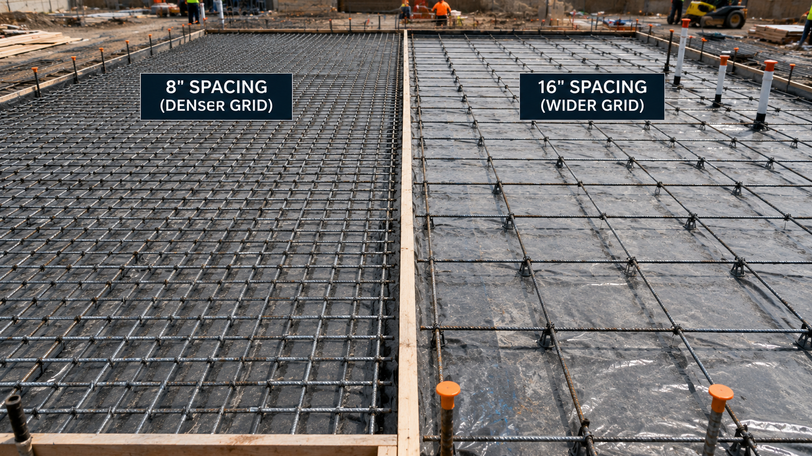
Rebar Area per Meter Chart
Metric equivalent reference using common spacings in millimeters, calculated with As = Ab times 1000 divided by spacing.
| Bar Size | 150 mm | 200 mm | 250 mm | 300 mm | 400 mm |
|---|---|---|---|---|---|
| #3 (#10) | 473 | 355 | 284 | 237 | 178 |
| #4 (#13) | 860 | 645 | 516 | 430 | 322 |
| #5 (#16) | 1333 | 1000 | 800 | 667 | 500 |
| #6 (#19) | 1893 | 1420 | 1136 | 947 | 710 |
| #8 (#25) | 3393 | 2545 | 2036 | 1697 | 1272 |
All values in mm2 per meter of width, rounded to the nearest whole number.
Rebar Size vs Area Comparison
This table isolates how much area increases from one common bar size to the next, focusing on cross-sectional area rather than weight.
| Comparison | Area Increase |
|---|---|
| #4 to #5 | 0.20 to 0.31 in.2 (+55%) |
| #5 to #6 | 0.31 to 0.44 in.2 (+42%) |
| #6 to #7 | 0.44 to 0.60 in.2 (+36%) |
| #7 to #8 | 0.60 to 0.79 in.2 (+32%) |
| #8 to #9 | 0.79 to 1.00 in.2 (+27%) |
| #9 to #10 | 1.00 to 1.27 in.2 (+27%) |
| #10 to #11 | 1.27 to 1.56 in.2 (+23%) |
Larger Bar vs Smaller Bar at Closer Spacing
Two different bar size and spacing combinations can produce different reinforcement areas even when they look superficially similar, so they cannot automatically be treated as equivalent.
| Layout | Area per Foot |
|---|---|
| #4 @ 8 in. | 0.300 in.2/ft |
| #5 @ 12 in. | 0.310 in.2/ft |
These two layouts produce nearly identical steel area per foot, but they are not automatically interchangeable. Total steel area, bar distribution across the width, crack control behavior, spacing limits, development length, and constructability all differ between the two layouts. Substitution decisions require full structural design evaluation, not just an area comparison.
Rebar Area and Reinforcement Ratio
The reinforcement ratio relates steel area to the concrete cross-section, used in structural design to characterize how heavily a member is reinforced.
- ρ = reinforcement ratio
- As = reinforcement area
- b = section width
- d = effective depth
Reinforcement ratio is a design concept that goes beyond bar area alone; it accounts for the concrete section dimensions the steel is embedded in. Area alone does not determine structural adequacy, since the same steel area can represent very different reinforcement ratios depending on the member’s width and depth. This page covers the concept only; full design should follow ACI CODE-318-25 provisions and a qualified structural design process.
Rebar Area for Concrete Slabs
Slabs use area per foot of width as the primary design quantity for both main flexural reinforcement and shrinkage/temperature reinforcement.
| Reinforcement Type | Governing Quantity |
|---|---|
| One-way slab main steel | Area per foot from bar size and spacing |
| Two-way slab reinforcement | Area per foot in each direction |
| Temperature/shrinkage steel | Minimum area per foot based on gross concrete area |
For spacing limits by slab thickness, see the Rebar Spacing Chart, and for thickness selection itself, see the Concrete Slab Thickness Chart.
Equipment for Your Project
Affiliate disclosure: As an Amazon Associate, ConcreteCalculate earns from qualifying purchases. We may also earn a commission from other affiliate links at no additional cost to you.
Rebar Area for Beams
Beams use total bar area, calculated by multiplying the number of bars by the area of one bar, for both tension and compression reinforcement.
- As = total steel area
- n = number of bars
- Ab = area of one bar
Beams often use multiple bars in one or more layers for both bottom (typically tension) and top (typically compression or negative moment) reinforcement. Total area from multiple bars is the starting design quantity, but bar count, layer arrangement, and clear spacing between bars all factor into the final detailing, covered in the Rebar Spacing Chart.
Rebar Area for Columns
Column longitudinal reinforcement area and transverse tie or spiral reinforcement area are separate concepts that should never be confused.
| Reinforcement | Area Concept |
|---|---|
| Longitudinal bars | Total area = n × Ab, compared against gross column area for reinforcement ratio |
| Ties/spirals | Separate transverse reinforcement area for confinement, not part of longitudinal steel area |
Rebar Area for Walls and Footings
Walls and footings both rely on area per unit width, calculated from bar size and spacing, for their primary reinforcement design quantity.
| Element | Reinforcement Direction |
|---|---|
| Walls | Vertical and horizontal area per foot of width |
| Footings | Two-way bottom reinforcement area per foot in each direction |
For footing dimension planning, see the Footing Size Chart, and for cover and bar positioning, see the Concrete Cover Chart.
Rebar Area and Minimum Reinforcement
Minimum reinforcement requirements exist for crack control, shrinkage and temperature effects, and structural performance, and vary by element and purpose.
No single universal minimum percentage
ACI CODE-318-25 is the current structural-concrete code and includes extensive reinforcement provisions, but the exact minimum reinforcement area depends on the specific structural member and reinforcement purpose, such as flexural reinforcement in a beam versus shrinkage and temperature reinforcement in a slab. Do not apply one minimum percentage across every application.
Rebar Area and Maximum Reinforcement
Structural design also limits how much reinforcement can be used in certain contexts, tied to ductility and tension-controlled behavior rather than a single fixed ratio.
Maximum reinforcement limits in structural concrete design relate to ensuring ductile, tension-controlled behavior rather than brittle failure modes, and the applicable limit depends on the member type, loading, and the specific code provisions governing that design context. There is no single universal maximum reinforcement ratio that applies across every structural element.
Rebar Area and Rebar Spacing
This is the most important relationship on this page: bar area combined with spacing determines the actual reinforcement area per unit width.
| Change | Effect on As per Foot |
|---|---|
| Larger bar, same spacing | Increases area per foot |
| Smaller bar, same spacing | Decreases area per foot |
| Same bar, closer spacing | Increases area per foot |
| Same bar, wider spacing | Decreases area per foot |
See the Rebar Spacing Chart for the minimum and maximum spacing rules that constrain which spacing values are actually permitted for a given bar size and application before this area relationship can be applied.
Rebar Area and Concrete Cover
Concrete cover does not change the physical cross-sectional area of a bar, but it affects effective depth and the structural capacity that area can contribute.
Cover positions the bar within the concrete section, which determines the effective depth (d) used in reinforcement ratio and capacity calculations. Two identical bars with identical area can contribute differently to structural capacity if their effective depth differs due to different cover requirements. See the Concrete Cover Chart for cover requirements by exposure condition.
Rebar Area and Development Length
Bar area affects development and anchorage length requirements, since larger bars generally require longer development lengths to transfer the same stress level into the surrounding concrete.
ACI CODE-318-25 continues to include dedicated requirements for development and anchorage of reinforcement, connecting bar area, bar diameter, and concrete strength to the embedment length needed for a bar to develop its full design strength. This page addresses the general concept only; see the Rebar Development Length Calculator for project-specific calculations.
Rebar Area and Lap Splices
Bar area remains unchanged by splicing; lap length is a separate development and anchorage concept, not an area calculation.
Splicing two bars together to extend length does not change the cross-sectional area of the reinforcement, but it does require an adequate lap length so force can transfer between the spliced bars. See the Rebar Lap Splice Chart for splice length and classification reference rather than duplicating that content here.
Rebar Area Substitution: Can One Bar Size Replace Another?
Substitution requires far more than comparing total area; every constraint below must also be satisfied.
Required steel area
The substitute layout must provide at least the required area, not just a similar area.
Minimum and maximum spacing
The new bar size and spacing combination must still satisfy applicable spacing limits.
Bar development
Larger bars need longer development lengths, which may not fit the available embedment.
Cover and constructability
Larger bars can affect cover positioning and placement feasibility in congested areas.
Structural design and code requirements
Any substitution should be verified against the full structural design and the applicable code edition, not assumed from an area comparison alone.
A common but incorrect assumption
Having more area than the original bar does not automatically make a substitution valid. “If #5 has more area than #4, you can always substitute it” ignores spacing limits, development length, and the full structural design context. Bar substitution should be approved by a qualified design professional or in accordance with approved project substitution procedures.
How to Calculate Total Rebar Area
Total area from a known number of bars is a simple multiplication, commonly used for beams and columns.
- n = number of bars
- Ab = area of one bar
Example: Four #8 Bars
How to Calculate Area From Spacing
This formula applies to distributed reinforcement in slabs and walls, where bar count is expressed through spacing rather than a fixed number.
This applies directly to a one-foot-wide strip of a slab or wall. To scale to the full width of a member, multiply the area per foot by the total width in feet, which is exactly the calculation the Rebar Grid Calculator automates for complete two-way grids.
Rebar Area Worked Examples
These examples teach the underlying math. They do not confirm structural adequacy for any project.
Find the Area of One Rebar
Find Total Area From Number of Bars
Calculate Area per Foot From Bar Size and Spacing
Compare Two Reinforcement Layouts
Rebar Area Standards and References
Four standards and industry references govern most rebar area data used in U.S. construction.
| Standard/Reference | Scope |
|---|---|
| ASTM A615/A615M | Standard specification for deformed and plain carbon-steel reinforcing bars, including standard bar sizes, dimensions, and number designations |
| ASTM A706/A706M | Low-alloy steel deformed and plain bars for concrete reinforcement, where weldability or controlled ductility is required |
| ACI CODE-318-25 | Current structural concrete code covering minimum requirements for materials, design, and detailing, including reinforcement provisions |
| CRSI | Concrete Reinforcing Steel Institute industry reference for standard bar sizes, diameters, areas, weights, detailing, and placement |
ACI’s current 318-25 materials identify changes involving closely spaced reinforcement groups and updated development/anchorage guidance, which is why the applicable code edition should always be confirmed for design work rather than assuming older editions remain current.
Rebar Area Chart Limitations
This chart is a reference and educational tool. It does not replace project-specific structural design.
Bar area is not required reinforcement area
Required area comes from a structural load and span calculation.
Larger area does not mean a better design
Distribution, spacing, and constructability all factor into design adequacy.
Bar size alone does not determine capacity
Concrete strength, steel grade, and geometry all affect capacity.
Cover and development length matter
Effective depth and anchorage both affect how bar area translates to capacity.
Applicable code edition matters
Always confirm which ACI 318 edition and project specifications govern the design.
Frequently Asked Questions
Download Rebar Area Chart PDF
Use your browser’s print function to save a curated, print-ready reference sheet: the quick-reference chart, area by size and spacing tables, formulas, worked examples, and diagrams, without navigation, FAQs, or explanatory prose. This avoids broken file links and stays automatically current.