Concrete Expansion Joints vs Control Joints: Differences, Uses and Installation
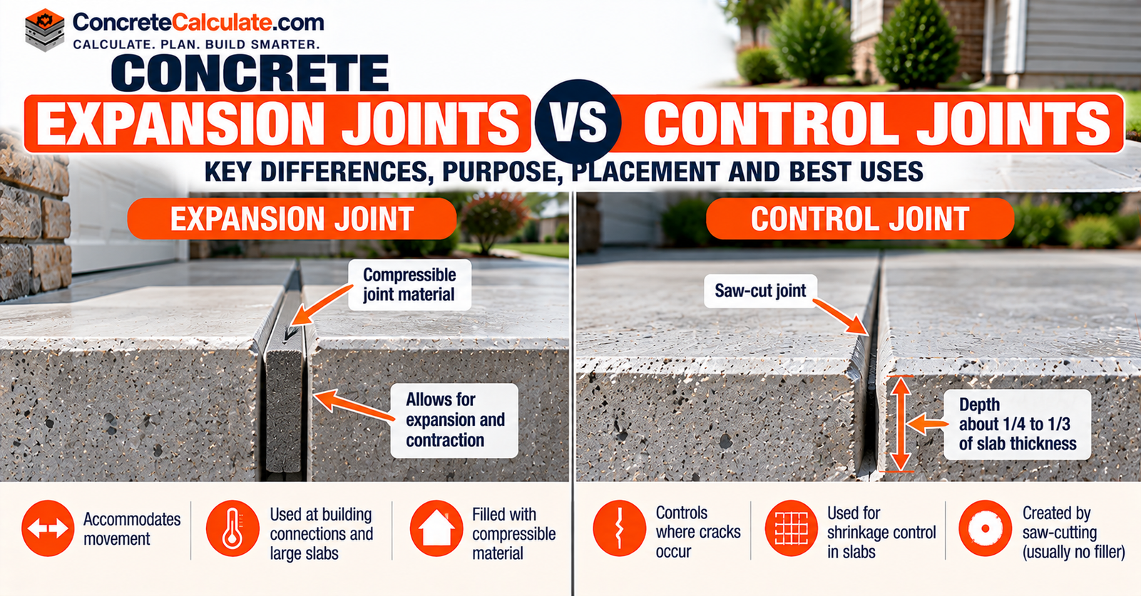
How contraction, isolation and expansion joints differ, where each one belongs, and how to plan a simple driveway or patio without mixing up the rules.
Quick Answer
A control joint, also called a contraction joint, is a partial-depth groove that creates a weakened plane so shrinkage cracking happens at a planned location instead of at random. An isolation joint is a full-depth separation that lets a slab move independently from an adjoining wall, column or structure.
An expansion joint is a designed separation that accommodates specified dimensional movement, and in residential slabs-on-ground it often looks similar to an isolation joint. A driveway typically needs interior contraction joints plus isolation where it meets a garage or house, not a series of full-depth expansion joints spaced like control joints.
| Joint Type | What It Does | Common Example |
|---|---|---|
| Control joint | Guides where shrinkage cracking occurs | Grooves spaced across a driveway or patio |
| Isolation joint | Separates a slab from an adjoining element | Where a patio meets a house foundation |
| Expansion joint | Accommodates specified dimensional movement | Engineered pavement or structural movement locations |
In This Guide
- 1. Concrete Expansion Joints vs. Control Joints: Quick Answer
- 2. What Is a Concrete Control Joint?
- 3. What Is a Concrete Expansion Joint?
- 4. What Is a Concrete Isolation Joint?
- 5. Expansion Joint vs. Control Joint vs. Isolation Joint
- 6. Why Does Concrete Need Different Types of Joints?
- 7. When Should You Use Control Joints?
- 8. When Should You Use Isolation Joints?
- 9. When Are True Expansion Joints Necessary?
- 10. Does a Concrete Slab Need Both Control and Isolation Joints?
- 11. Concrete Driveway Joints: Where Does Each Type Go?
- 12. Patio and Pool Deck Joints: Control or Isolation?
- 13. Sidewalk and Walkway Joints
- 14. Garage Floors, Basement Slabs and Industrial Floors
- 15. Control Joint vs. Expansion Joint Depth
- 16. How Wide Should Each Type of Joint Be?
- 17. Control Joint Spacing vs. Expansion Joint Spacing
- 18. How Panel Shape Affects Control Joint Layout
- 19. Where Should Joints Go at Corners, Columns and Openings?
- 20. Worked Example: Joint Layout for a 20 x 12-Foot Patio
- 21. How Are Control Joints Installed?
- 22. How Are Expansion and Isolation Joints Installed?
- 23. Expansion Joint Filler vs. Control Joint Sealant
- 24. Should Joints Be Sealed, Filled or Left Open?
- 25. Can Rebar or Dowels Cross a Control or Expansion Joint?
- 26. Common Joint Installation Mistakes and Their Consequences
- 27. How to Inspect, Repair and Maintain Existing Concrete Joints
- 28. Concrete Expansion Joints vs. Control Joints FAQs
1. Concrete Expansion Joints vs. Control Joints: Quick Answer
A control joint establishes a preferred cracking location within a slab, while a full-depth movement joint separates concrete elements entirely. These are fundamentally different jobs, even though both get lumped together as joints in everyday conversation.
Isolation and expansion joints are closely related but not identical. An isolation joint separates a slab from an adjoining wall, column or structure so they can move independently, while a true expansion joint is a designed separation sized for specified dimensional movement, most often seen in engineered pavements and structures rather than ordinary residential slabs.
A recognizable example of each: a saw-cut groove across a driveway is a control joint, and the gap where that driveway meets the garage floor is typically an isolation joint. The Concrete Joint Calculator can help estimate interior joint quantities once you understand which measurements it’s actually calculating.
2. What Is a Concrete Control Joint?
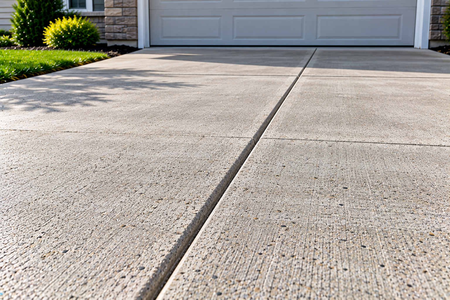
A control joint, also called a contraction joint, is a formed, sawed or tooled groove that creates a weakened plane in the concrete. That weakened plane encourages the slab to crack along a planned line as it shrinks, rather than cracking randomly across the surface.
The intended crack develops beneath the groove as the concrete undergoes drying shrinkage and thermal contraction. A properly designed contraction joint pattern reduces undesirable, random cracking, but it doesn’t guarantee a completely crack-free surface.
3. What Is a Concrete Expansion Joint?
According to ACI’s technical guidance, an expansion joint is a separation provided between adjacent sections of a concrete structure to allow movement from dimensional increases and reductions, and some or all of the bonded reinforcement is interrupted through it. In pavement slabs on ground, it typically means a separation between slabs filled with a compressible filler material.
Concrete expands and contracts with temperature changes, and a genuine expansion joint is engineered to accommodate that specific movement. Ordinary residential slabs-on-ground rarely need true expansion joints the way longer pavements, bridges and other engineered structures do, since those larger structures experience more significant cumulative thermal movement over greater distances.
4. What Is a Concrete Isolation Joint?
ACI defines an isolation joint as a separation between adjacent sections of a concrete structure that allows relative movement in three directions, and through which all of the bonded reinforcement is interrupted. A slab often needs to move independently of a wall, column, foundation or adjoining slab that won’t move the same way it does.
Isolation joints use a full-depth separation with a compressible filler material running the entire thickness of the slab. In residential construction, isolation joints are commonly called expansion joints in casual conversation, even though the precise ACI terminology treats them as related but distinct concepts.
5. Expansion Joint vs. Control Joint vs. Isolation Joint
This table is the article’s main technical reference, comparing all three joint types side by side.
| Feature | Control/Contraction Joint | Isolation Joint | Expansion Joint |
|---|---|---|---|
| Primary purpose | Encourage cracking at a planned location | Permit independent movement from an adjoining element | Accommodate specified dimensional movement |
| Typical residential location | Within a driveway or patio | At a wall, column or adjoining slab where required | Where specifically designed, may coincide with isolation details |
| Typical depth | Partial-depth groove | Full-depth separation | Designed separation, commonly full-depth in applicable details |
| Main material or detail | Saw cut, tooled groove or formed joint | Specified separation and compressible filler | Designed gap with appropriate movement-joint materials |
| Spacing method | Based on slab design, thickness and geometry | Based on locations requiring separation | Based on anticipated movement and project design |
| Main mistake | Too shallow or incorrectly located | Inadvertent concrete or reinforcement connection | Assuming contraction-joint spacing rules apply |
Terminology may be simplified in residential product labeling, whereas professional drawings should identify the intended function precisely. A construction joint, the interface where separate concrete placements meet, is not automatically an expansion joint just because it’s a break in the pour.
6. Why Does Concrete Need Different Types of Joints?
Drying shrinkage, temperature-related movement, restraint from adjoining elements, differential movement between structures, and concrete’s relatively limited tensile capacity all create the need for planned joints. Concrete resists compression well but resists being pulled apart far less effectively, so when shrinkage or thermal stress builds up, it cracks.
Consider a patio poured next to a house. The concrete inside the patio panel tends to shrink as it cures, while the adjoining house foundation provides a fixed restraint that doesn’t shrink the same way, which is exactly why the patio may need to be isolated from that restraint.
Not every crack is the result of a missing expansion joint. Many cracks relate to contraction-joint spacing, panel shape or subgrade support instead, so it helps to diagnose the actual cause before assuming a movement joint was the missing piece.
7. When Should You Use Control Joints?
Control joints are relevant for jointed slabs-on-ground, including patios, driveways, sidewalks and appropriate interior floor slabs. A planned contraction-joint pattern makes sense whenever ordinary shrinkage cracking needs to be directed to specific locations rather than left to occur randomly.
Engineered or specialized slab systems, such as continuously reinforced or post-tensioned slabs, follow different design approaches and shouldn’t automatically be jointed using general residential guidance.
8. When Should You Use Isolation Joints?
Common conditions calling for isolation include slab-to-wall connections, slab-to-column locations, driveway-to-garage transitions and patio-to-existing-structure interfaces. ACI recommends isolation joints at the junction of slabs and walls, columns, equipment foundations, footings and other points of restraint.
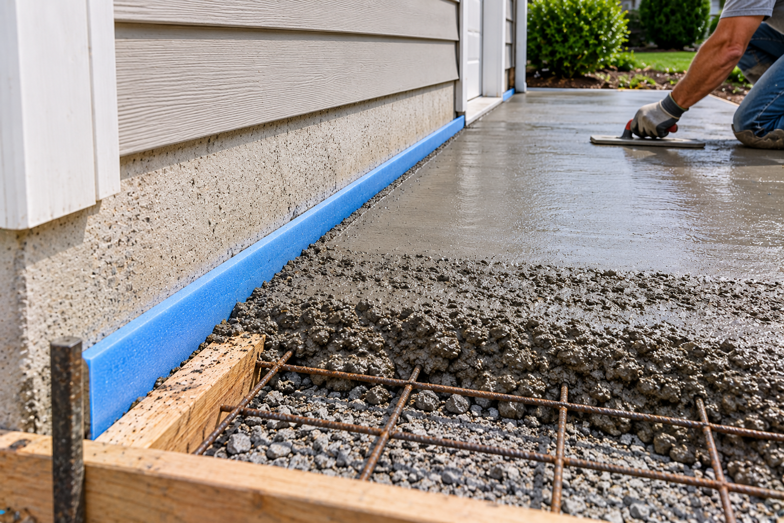
The exact location and detail depend on the actual restraint present and the intended movement, so not every slab perimeter automatically needs the same full-depth filler treatment on all sides.
9. When Are True Expansion Joints Necessary?
True, engineered expansion joints matter most in structures or pavement systems where significant thermal or other movement must be deliberately accommodated across longer runs, such as highway pavements, bridge decks and large commercial or industrial structures. Ordinary residential slabs rarely experience that scale of cumulative movement.
Readers should not automatically insert regularly spaced full-depth expansion joints throughout an ordinary driveway or patio. Where a project actually has drawings or an engineered movement-joint schedule, those documents determine the real requirements, not a general residential rule of thumb.
10. Does a Concrete Slab Need Both Control and Isolation Joints?
Often, yes. An ordinary patio adjoining a house may need isolation at the building line to allow independent movement, plus a planned pattern of contraction joints within the patio itself to control shrinkage cracking in the field of the slab.
These two details perform genuinely separate functions. A contraction joint won’t isolate a slab from a wall, and an isolation joint won’t control where the interior of the slab cracks, so one shouldn’t be substituted for the other.
11. Concrete Driveway Joints: Where Does Each Type Go?
A driveway meeting a garage floor and a sidewalk illustrates all three joint concepts working together in one everyday example.
| Location | Joint or Detail to Evaluate | Main Reason |
|---|---|---|
| Within a rectangular patio | Contraction joint | Guide shrinkage cracking |
| Patio next to a building wall | Isolation joint where required | Separate the patio from the building |
| Driveway adjoining garage slab | Isolation or specified interface detail | Accommodate relative movement |
| Around a structural column | Isolation joint | Avoid restraint and accommodate independent movement |
| Within a sidewalk run | Contraction joint | Establish planned cracking locations |
| Where two placements meet | Planned construction-joint detail | Accommodate the construction sequence and required structural behavior |
| Engineered long-run pavement location | Specified expansion-joint detail | Accommodate design movement |
This table is a selection guide, not a substitute for construction drawings. Planned interior contraction joints handle the driveway’s own shrinkage, while the garage threshold and any adjoining sidewalk or curb need their own site-specific check for movement and load-transfer requirements.
12. Patio and Pool Deck Joints: Control or Isolation?
The joints inside a patio serve a different purpose than the isolation needed at a house wall, column or other restraint. Irregular patio geometry, re-entrant corners and pool shells all add complexity beyond a simple rectangular layout.
Pool decks in particular often sit adjacent to a structure that can move independently of the surrounding deck, and pool-deck isolation and waterproofing details need to follow the specific pool design rather than a generic patio rule.
13. Sidewalk and Walkway Joints
Transverse contraction joints are commonly planned within walkways, typically spaced according to the walkway’s width and the slab thickness. Additional attention is needed where a sidewalk intersects a driveway, meets steps, or runs into another constraint.
Matching joint layout to the walkway’s specific width and geometry makes sense, but no single joint spacing should be presented as universally mandatory for every sidewalk.
14. Garage Floors, Basement Slabs and Industrial Floors
Indoor residential slabs generally follow the same general jointing considerations as other slabs-on-ground. Industrial floors subject to hard-wheeled traffic are a different matter, since load transfer, joint-edge protection and curling behavior all become more significant concerns.
Special industrial slab designs, including specific joint spacing and edge protection details, shouldn’t be reduced to a simple residential driveway formula.
15. Control Joint vs. Expansion Joint Depth
The fundamental geometry differs sharply between these joint types. A conventional contraction joint is ordinarily a partial-depth groove, while an isolation or expansion joint is a full-depth separation that passes completely through the slab.
NRMCA’s general guidance for ordinary contraction joints calls for a minimum groove depth of one-quarter of the slab thickness, with a floor of at least 1 inch even on thinner slabs. This general recommendation has real limits when applied to early-entry saw systems or engineered slabs, which may follow different manufacturer or design-specific depth requirements.
16. How Wide Should Each Type of Joint Be?
A saw-cut groove’s width is fundamentally different from the separation width a movement joint needs, since they serve different purposes. Groove width relates mainly to the saw blade and any sealant reservoir cut, while movement-joint width depends on expected movement, the compressible filler selected, and the sealant’s geometry requirements.
A nominal half-inch isolation filler is a useful illustration of typical residential practice, but it shouldn’t be promoted as a universal design width, since the actual required width depends on anticipated movement and the manufacturer’s specifications for the selected filler and sealant system.
17. Control Joint Spacing vs. Expansion Joint Spacing
The Critical Distinction
Slab-thickness spacing multipliers are general contraction-joint planning guidance. They are not a universal formula for expansion-joint spacing, and applying them that way is one of the most common mistakes in residential joint planning.
| Slab Thickness | Calculated 24x to 36x Contraction-Joint Spacing | Conventional Minimum Groove Depth |
|---|---|---|
| 4 in | 8 to 12 ft | 1 in |
| 5 in | 10 to 15 ft | 1.25 in |
| 6 in | 12 to 18 ft, check the recommended 15-ft limit | 1.5 in |
| 8 in | 16 to 24 ft, requires a more specific design review | 2 in |
Use the following NRMCA general slab-on-ground guidance, subject to project requirements. The 15-ft figure is its recommended upper spacing limit, not a universally applicable code limit. None of these spacing values establishes a required interval for full-depth expansion joints.
Full-depth expansion joints are positioned and sized according to anticipated movement and the applicable engineered design, not the contraction-joint thickness multiplier. Confusing the two leads directly to the mistake of installing full-depth movement joints at regular contraction-joint intervals where none are actually needed.
18. How Panel Shape Affects Control Joint Layout
Square or nearly square panels resist random cracking better than long, narrow ones. NRMCA recommends a length-to-width ratio no greater than 1.5 to 1 for applicable general slab guidance, and advises avoiding L-shaped panels.
The complete joint-layout procedure, including detailed spacing calculations and panel-shape checks, remains on the dedicated Concrete Control Joints guide, since this article focuses on the comparison between joint types rather than repeating that full procedure.
19. Where Should Joints Go at Corners, Columns and Openings?
Re-entrant corners, meaning inside corners where an L or T shape cuts into a slab, concentrate stress regardless of the nearest planned joint. Columns need isolation to address the fixed restraint they create, and that isolation detail intersects with the surrounding contraction-joint pattern in ways that need coordination.
A column or an inside corner needs an appropriate, purpose-built detail rather than merely an arbitrary extra saw cut placed nearby.
20. Worked Example: Joint Layout for a 20 x 12-Foot Patio
Here’s a practical plan for a hypothetical 4-inch patio adjoining a house along its 20-foot side, showing how contraction joints and an isolation joint work together.
| Item | Illustrative Value |
|---|---|
| Patio dimensions | 20 x 12 ft |
| Patio thickness | 4 in |
| Isolation length along house | 20 linear ft |
| Interior contraction-joint runs across the 12-ft width | 2 x 12 = 24 linear ft |
| Interior contraction-joint run parallel to house | 1 x 20 = 20 linear ft |
| Total interior contraction joints | 44 linear ft |
| Number of panels | 6 |
| Approximate panel dimensions | 6.67 x 6 ft |
| Approximate panel aspect ratio | 1.11:1 |
This layout demonstrates how contraction joints and a separate isolation joint can coexist in one project. It’s an illustrative jointing concept, not a project-specific structural design. Other restraints, openings, site conditions and structural requirements may change the actual plan, and the other three perimeter edges don’t automatically need the same isolation treatment shown at the house side.
21. How Are Control Joints Installed?
Control joints are installed using one of three principal methods: tooling a groove by hand while the concrete is still plastic, saw-cutting after the surface has gained adequate firmness, or using a suitable formed joint system placed before the pour.
The dedicated Concrete Control Joints guide covers detailed equipment selection, spacing calculations and saw-timing instructions in full, so this comparison article keeps that discussion brief.
22. How Are Expansion and Isolation Joints Installed?
Isolation and expansion joints are established by placing a continuous separation using the specified preformed filler or other engineered detail, typically positioned before or during the concrete placement itself. Keeping the filler properly aligned and maintaining the intended separation throughout the pour matters just as much as selecting the right material.
Avoid unplanned concrete bridges, spots where wet concrete flows over or around the filler and creates an accidental rigid connection, and prepare any required sealant recess at the top of the joint if the design calls for one. An ordinary shallow saw cut cannot create an effective full-depth isolation joint by itself, no matter how it’s finished at the surface.
23. Expansion Joint Filler vs. Control Joint Sealant
These are different components serving different functions, and mixing them up leads to real performance problems.
| Material | Main Function | Appropriate Consideration |
|---|---|---|
| Asphalt-based preformed filler | Compressible separation in compatible movement-joint details | Check the specified ASTM designation and exposure |
| Sponge-rubber or cork filler | Compressible joint filling | Confirm compression and recovery requirements |
| Polyethylene foam filler | Separation in appropriate applications | Confirm product suitability and compressibility |
| Backer rod | Controls sealant depth and supports proper sealant geometry | Select compatible diameter and type |
| Elastomeric joint sealant | Forms a flexible seal against moisture and debris | Match movement capability, exposure and joint geometry |
| Semi-rigid joint filler | Supports joint edges in suitable traffic-bearing floors | Generally not a substitute for flexible expansion-joint sealant |
ASTM D1751 covers nonextruding, resilient asphalt-based preformed expansion-joint filler for use in concrete construction. ASTM D1752 addresses preformed sponge rubber, cork and recycled-PVC expansion joint fillers as alternative specified materials for the same general purpose.
24. Should Joints Be Sealed, Filled or Left Open?
Exterior joints exposed to moisture and debris generally benefit from an appropriate flexible sealant, while some ordinary contraction joints in less exposed locations may remain unsealed without significant issue.
Flexible movement-joint sealants and semi-rigid joint-edge fillers serve different purposes. Semi-rigid fillers work well protecting joint edges in suitable industrial-floor applications carrying hard-wheeled traffic, but an incompatible rigid filler placed in a joint that’s actually intended to move can interfere with that movement and cause new distress.
25. Can Rebar or Dowels Cross a Control or Expansion Joint?
Reinforcement continuity that runs unbroken across a joint can restrain the very movement that joint is meant to allow, which is a problem specifically at isolation and expansion joints, where ACI’s terminology confirms that all or some bonded reinforcement should be interrupted. Appropriately designed dowels, by contrast, may be used at certain joints specifically where load transfer is required, following approved structural details.
Contraction, isolation, expansion and construction joints each handle reinforcement differently at a conceptual level, and getting this wrong defeats the purpose of the joint. Don’t cut embedded reinforcement or add dowels without following the approved structural details for your specific project, since improvised changes here can create real structural issues.
26. Common Joint Installation Mistakes and Their Consequences
| Mistake | Consequence | Prevention or Correction |
|---|---|---|
| Using a shallow groove instead of a full-depth separation | Isolation joint fails to actually isolate the slab | Confirm full-depth separation at required restraint locations |
| Spacing expansion joints by the contraction-joint formula | Unnecessary full-depth joints or missed actual movement locations | Base expansion-joint placement on the applicable design, not slab thickness alone |
| Sawing contraction joints too late | Random, uncontrolled cracking before the cut is made | Cut once the surface can withstand the saw, before shrinkage cracking begins |
| Inadequate groove depth | Joint fails to control the crack location | Verify depth against the applicable minimum for the slab thickness |
| Poorly proportioned panels | Increased risk of random cracking within long, narrow panels | Keep panel aspect ratio within the recommended range |
| Missing column isolation | Restraint at the column causes unplanned cracking nearby | Add the appropriate isolation detail at every restraint point |
| Using an unsuitable filler | Rigid material blocks intended movement, causing distress | Match filler and sealant selection to the joint’s actual function |
27. How to Inspect, Repair and Maintain Existing Concrete Joints
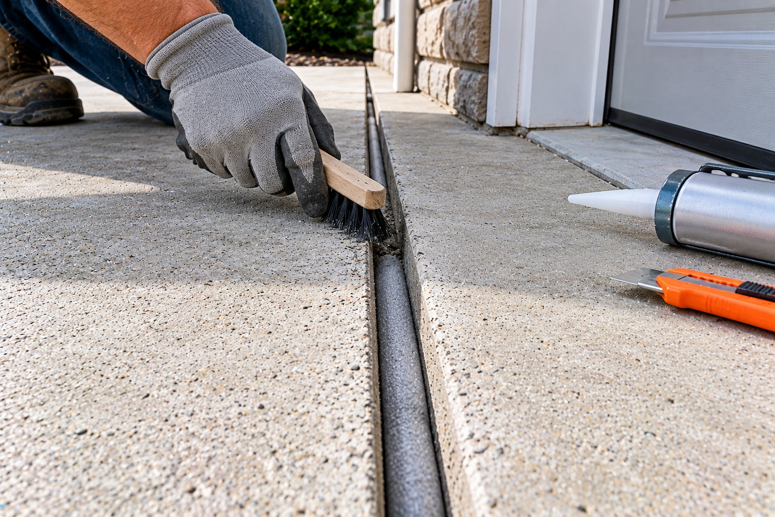
Look for damaged joint edges, failed or missing sealant, vegetation growing in the joint, trapped debris preventing proper closure, widening cracks and any sign of differential movement between adjacent slab sections.
Routine maintenance, such as replacing a compatible sealant or clearing debris, is something most homeowners can handle themselves. Significant displacement, severe spalling at the joint edge, or any sign of ongoing structural movement calls for professional diagnosis rather than a simple maintenance fix.
28. Concrete Expansion Joints vs. Control Joints FAQs
Are both control joints and expansion joints necessary?
Often yes, but they serve different purposes. A typical patio needs interior contraction joints for shrinkage control and isolation where it meets a fixed restraint like a house wall, as explained in section 10.
Do control joints allow concrete to expand?
Not really. Control joints are designed to manage shrinkage cracking, not to accommodate significant expansion, which is the role of an isolation or expansion joint instead, as covered in section 5.
Where do expansion joints go in a driveway?
Genuine expansion joints are uncommon in ordinary residential driveways. What most driveways actually need is isolation where they meet a garage floor or sidewalk, discussed in section 11.
Can a full-depth joint be retrofitted into an existing slab?
It’s possible in some cases but more involved than cutting a new contraction joint, since it requires creating a genuine full-depth separation and installing compressible filler, as described in section 22.
How can I tell which type of joint I already have?
Check the depth and material. A shallow groove with no filler is a contraction joint, while a full-depth gap with compressible filler is an isolation or expansion joint, as outlined in section 15.
Do control joints need sealant?
Not always. Some contraction joints in less exposed locations can remain unsealed, while joints exposed to significant moisture and debris generally benefit from a compatible flexible sealant, as explained in section 24.
Why do cracks sometimes appear beside a correctly installed joint?
This can happen due to restraint, subgrade issues, panel shape or a nearby re-entrant corner that the joint pattern didn’t fully address, covered in section 19 and section 26.
Is an isolation joint the same as an expansion joint?
They’re closely related and often used interchangeably in casual conversation, but ACI’s precise terminology treats them as related, distinct concepts, as explained in section 4.
References
- American Concrete Institute, Technical FAQ: Difference Between a Contraction Joint, Isolation Joint, Expansion Joint, Construction Joint and Cold Joint. Primary source for precise joint terminology and definitions used throughout this guide.
- National Ready Mixed Concrete Association, CIP 6, Joints in Concrete Slabs on Grade. Principal practical reference for ordinary slab jointing, general contraction-joint spacing, groove depth, panel geometry and isolation locations.
- American Concrete Institute, ACI 224.3R-95, Joints in Concrete Construction. Technical reference for differences among joint functions, detailing and the relationship between slab isolation and expansion. Confirm the applicable edition and complete report for any numerical provisions.
- ASTM D1751-23, Standard Specification for Preformed Expansion Joint Filler for Concrete Paving and Structural Construction. Reference for nonextruding, resilient asphalt-based preformed filler materials.
- ASTM D1752-18(2023), Standard Specification for Preformed Sponge Rubber, Cork and Recycled PVC Expansion Joint Fillers for Concrete Paving and Structural Construction. Supporting reference for alternative specified joint-filler materials.