
HDPE SDR Chart: DR 11, 13.5, 17 & Pressure Ratings
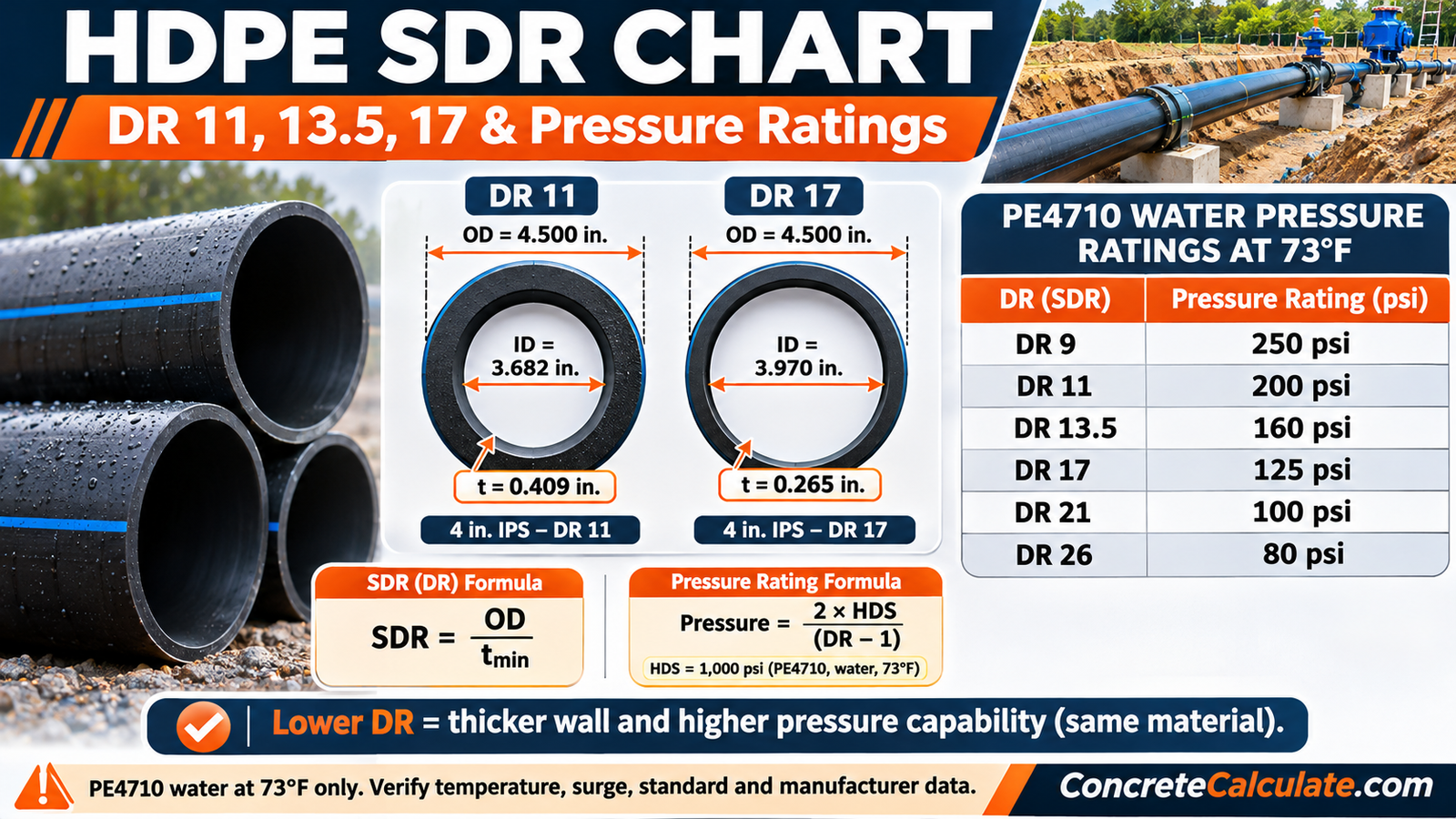
Standard dimension ratios, wall thickness, PE4710 water pressure ratings at 73°F, IPS and DIPS sizing, and inside-diameter methods for HDPE pipe.
 Reviewed by Muhammad Ramzan Babar, PhD Researcher (Plasma Physics) & Calculator Developer. View Profile
⭐ HDPE SDR Chart
An HDPE SDR chart shows how outside diameter divided by minimum wall sets pipe wall thickness: DR 11 has a wall of OD ÷ 11 and DR 17 has OD ÷ 17. For PE4710 water pipe at 73°F, DR 11 is rated 200 psi and DR 17 is rated 125 psi.
Standard SDR/DR Ratios and PE4710 Water Pressure Ratings
| HDPE SDR/DR | Minimum wall as fraction of OD | Approx. wall as % of OD | Calculated 2·HDS ÷ (DR – 1) (psi) | Standard PE4710 water pressure rating at 73°F (psi) |
|---|---|---|---|---|
| 7.3 | OD ÷ 7.3 | 13.70% | 317.5 | about 317 to 318 |
| 9 | OD ÷ 9 | 11.11% | 250.0 | 250 |
| 11 | OD ÷ 11 | 9.09% | 200.0 | 200 |
| 13.5 | OD ÷ 13.5 | 7.41% | 160.0 | 160 |
| 17 | OD ÷ 17 | 5.88% | 125.0 | 125 |
| 21 | OD ÷ 21 | 4.76% | 100.0 | 100 |
| 26 | OD ÷ 26 | 3.85% | 80.0 | 80 |
| 32.5 | OD ÷ 32.5 | 3.08% | 63.5 | 63 |
Source: preferred SDR series from the PPI Standard Dimension Ratio page; standard water pressure ratings (250, 200, 160, 125, 100, 80, 63, 50, 40 psi) from the PPI Handbook of Polyethylene Pipe, Chapter 6. Percentages are 100 ÷ DR. DR 7.3 calculates to 317.5 psi and manufacturers list 317 or 318 psi; it is not one of PPI’s rounded standard ratings.
✓ Checked against the PPI Standard Dimension Ratio page and PPI Handbook (Chapter 6), November 2026Reference conditions only
Pressure ratings apply to PE4710 water piping at 73°F (23°C) with HDS = 1,000 psi. They do not automatically apply to other PE grades, elevated temperatures, fuel gas, chemicals, nonpressure conduit, pressure surges, or every manufacturer product. Verify the ASTM or AWWA standard, manufacturer data, and application requirements.
Not every ratio is available in every nominal size. Production ranges depend on the pipe standard and the manufacturer. For full size tables see the HDPE Pipe Size Chart.
What Does SDR Mean in HDPE Pipe?
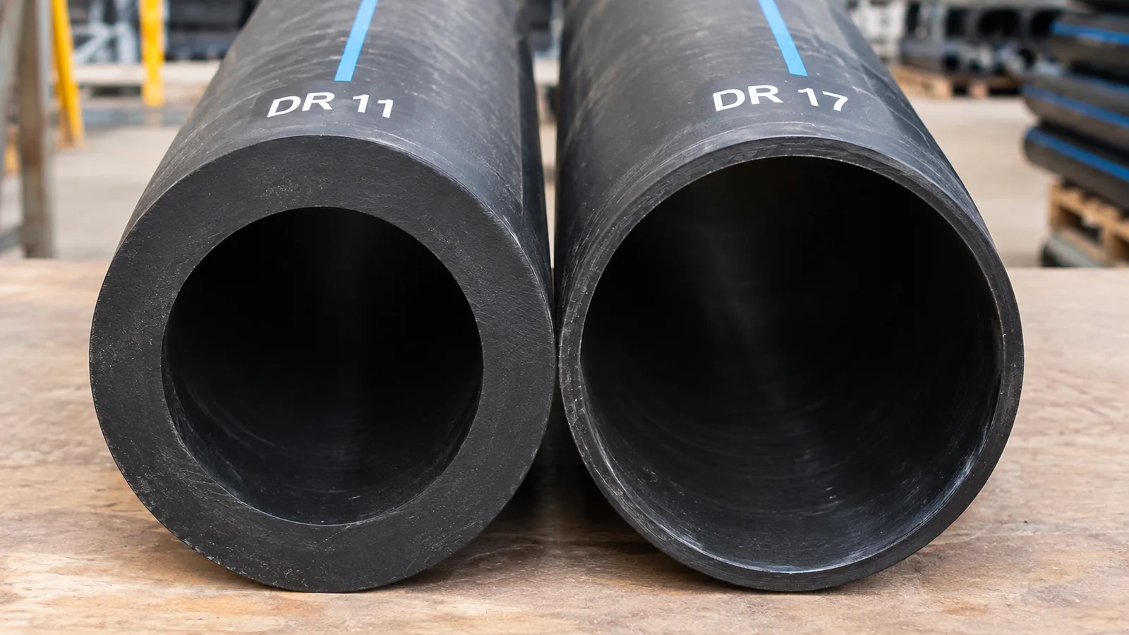
SDR is the ratio of an HDPE pipe’s outside diameter to its minimum wall thickness, so a lower SDR means a thicker wall for the same outside diameter.
The formula is SDR = OD ÷ t_min. A 4.500 in. OD pipe at SDR 11 has a minimum wall of 4.500 ÷ 11 = 0.409 in. Because it is a ratio, the same DR gives the same pressure rating at every diameter for the same material and application (PPI Standard Dimension Ratio page).
SDR is geometry, not a pressure rating
Pressure capability also depends on the polyethylene material, temperature, and service conditions. SDR is also not the same as nominal pipe size or a schedule number.
SDR vs. DR vs. SIDR
DR is the general ratio of outside diameter to minimum wall, SDR is a standardized series of DR values (7.3, 9, 11, 13.5, 17, 21, 26, 32.5), and SIDR applies to inside-diameter-controlled pipe.
- DR: OD ÷ minimum wall, any value.
- SDR: a DR that matches the preferred number series, such as 11 or 17. Industry often uses the terms interchangeably, so keep the designation printed on the pipe.
- SIDR: inside-diameter-controlled pipe uses IDR = ID ÷ t. The PPI pressure formula for ID-controlled pipe differs from the OD-controlled form, so do not use 2·HDS ÷ (DR – 1) unchanged for SIDR pipe.
How to Read the HDPE SDR Chart
To read an HDPE SDR chart, confirm the pipe material, the sizing system, the ratio, and the temperature, then read the wall thickness and pressure rating for that ratio.
- Identify the pipe material: the chart is for PE4710 water pipe.
- Verify the sizing system: IPS, DIPS, or metric.
- Read the ratio in the first column.
- Find the wall thickness: OD ÷ DR.
- Check the pressure rating and its 73°F assumption.
A pipe’s printed marking shows the material, DR, size, and standard needed for this check (see Section 21).
Common HDPE SDR Ratings
The common PE4710 water ratios run from DR 7.3 (thick wall, about 317 psi) to DR 32.5 (thin wall, 63 psi), with DR 9, 11, 13.5, and 17 rated 250, 200, 160, and 125 psi.
| HDPE SDR/DR | Min wall, 4 in. IPS (OD 4.500 in.) | Min wall, 6 in. IPS (OD 6.625 in.) | PE4710 water rating at 73°F (psi) |
|---|---|---|---|
| 7.3 | 0.616 | 0.908 | about 317 to 318 |
| 9 | 0.500 | 0.736 | 250 |
| 11 | 0.409 | 0.602 | 200 |
| 13.5 | 0.333 | 0.491 | 160 |
| 17 | 0.265 | 0.390 | 125 |
| 21 | 0.214 | 0.315 | 100 |
| 26 | 0.173 | 0.255 | 80 |
| 32.5 | 0.138 | 0.204 | 63 |
Walls calculated as OD ÷ DR and shown to three decimals; use the product standard for specified values and rounding. Ratings as in Section 1.
✓ Calculated from stated dimensions, arithmetic checked, November 2026SDR 7.3, 9, 11, 13.5, 17, 21, 26, and 32.5
Each step is about 25% in wall thickness (see Section 7). Availability varies by size and manufacturer, and some ratios are not made in every diameter.
⭐ SDR 11 vs. SDR 17 HDPE Pipe
At the same outside diameter, SDR 11 has about 54.5% more minimum wall than SDR 17 (17 ÷ 11 = 1.545), and under PE4710 water conditions it is rated 200 psi against 125 psi.
| Property | SDR 11 | SDR 17 |
|---|---|---|
| Wall-thickness ratio | OD ÷ 11 | OD ÷ 17 |
| Approx. wall thickness / OD | 9.09% | 5.88% |
| PE4710 pressure rating at 73°F | 200 psi | 125 psi |
| Relative wall thickness at same OD | Thicker | Thinner |
| Approx. inside flow space at same OD | Smaller | Larger |
Wall percentages are 100 ÷ DR. Ratings are for PE4710 water at 73°F (HDS 1,000 psi).
✓ Calculated from stated dimensions, arithmetic checked, November 2026The wall ratio and the pressure ratio are different numbers: 17 ÷ 11 = 1.545, while 200 ÷ 125 = 1.60. Pressure follows 2·HDS ÷ (DR – 1), not wall thickness alone. A thicker wall also leaves a smaller bore, so the choice depends on pressure, hydraulics, and installation. See the How to Choose HDPE Pipe SDR guide.
HDPE SDR vs. Minimum Wall Thickness
Minimum wall thickness is inversely proportional to DR, t = OD ÷ DR, so each step down the standard series adds roughly 22% to 26% to the wall at the same outside diameter.
| Ratio step (DR) | Wall ratio (thicker ÷ thinner) | Approx. increase |
|---|---|---|
| 7.3 to 9 | 1.233 | about 23% |
| 9 to 11 | 1.222 | about 22% |
| 11 to 13.5 | 1.227 | about 23% |
| 13.5 to 17 | 1.259 | about 26% |
| 17 to 21 | 1.235 | about 24% |
| 21 to 26 | 1.238 | about 24% |
| 26 to 32.5 | 1.250 | about 25% |
Calculated as DR(thin) ÷ DR(thick). The PPI Standard Dimension Ratio page states there is approximately 25% difference in minimum wall between each SDR.
✓ Checked against the PPI statement of about 25% wall difference per SDR, November 2026Minimum wall is not average wall. PPI treats wall thickness as a minimum with a plus 12% tolerance, so the average wall used for an average inside diameter is the minimum plus 6% (PPI Handbook of Polyethylene Pipe, Chapter 6).
⭐ HDPE SDR Wall Thickness Chart by IPS Size
A 4 in. IPS HDPE pipe (4.500 in. OD) has a calculated minimum wall of 0.409 in. at DR 11, 0.333 in. at DR 13.5, 0.265 in. at DR 17, and 0.214 in. at DR 21.
| IPS nominal size (OD) | DR 11 wall | DR 13.5 wall | DR 17 wall | DR 21 wall |
|---|---|---|---|---|
| 4 in. (4.500 in.) | 0.409 in. | 0.333 in. | 0.265 in. | 0.214 in. |
| 6 in. (6.625 in.) | 0.602 in. | 0.491 in. | 0.390 in. | 0.315 in. |
| 8 in. (8.625 in.) | 0.784 in. | 0.639 in. | 0.507 in. | 0.411 in. |
| 12 in. (12.750 in.) | 1.159 in. | 0.944 in. | 0.750 in. | 0.607 in. |
IPS outside diameters 4.500, 6.625, 8.625, and 12.750 in. (ASTM F714 sizing). Unrounded relationships shown to three decimals. For procurement or compliance use the standard’s dimension table and its rounding and tolerances; never round a required minimum wall down and treat it as compliant.
✓ Calculated from stated dimensions, arithmetic checked, November 2026This compact table explains the relationship without duplicating the full HDPE Pipe Size Chart. For multi-material wall data, see the Pipe Wall Thickness Chart.
⭐ HDPE SDR vs. Pressure Rating
HDPE pressure rating follows PR = 2·HDS ÷ (DR – 1), so for PE4710 water pipe with HDS = 1,000 psi, DR 17 is 125 psi and DR 11 is 200 psi at 73°F.
| DR | Pressure rating at 73°F, HDS 1,000 psi (psi) | Calculated 2·HDS ÷ (DR – 1) (psi) |
|---|---|---|
| 9 | 250 | 250.0 |
| 11 | 200 | 200.0 |
| 13.5 | 160 | 160.0 |
| 17 | 125 | 125.0 |
| 21 | 100 | 100.0 |
| 26 | 80 | 80.0 |
Source: PPI Handbook of Polyethylene Pipe, Chapter 6. PE4710 DR 9, 11, 13.5, and 17 values of 250, 200, 160, and 125 psi are also given in the PPI Anchor Block Report and the Alliance for PE Pipe engineering package (Alliance for PE Pipe Engineer’s Package).
✓ Checked against the PPI Standard Dimension Ratio page and PPI Handbook (Chapter 6), November 2026PE4710 DR 17 pressure rating
This matches the PPI standard rating for the cited reference case. It does not include surges, external loads, fittings, temperature, or installation defects.
PPI and AWWA use the terms pressure rating and pressure class. AWWA pressure class is described as capacity to resist working pressure up to 80°F including specified recurring-surge allowances. A class is not the same as hydrostatic test pressure, burst pressure, or a maximum for all service conditions.
⭐ PE4710 and Hydrostatic Design Stress
PE4710 water pipe uses a hydrostatic design stress of 1,000 psi at 73°F, which is why DR 11 rates 200 psi, and HDS must not be confused with HDB.
| Term | Meaning | PE4710 water example |
|---|---|---|
| HDB (hydrostatic design basis) | Categorized long-term hoop-stress strength at a stated temperature | Listed by PPI in TR-4 |
| HDS (hydrostatic design stress) | HDB reduced by a design factor | 1,000 psi at 73°F |
| Design factor | Applied to HDB for water service | 0.63 for PE4710 (PPI TR-9) |
| Designation code | Last two digits give HDS in hundreds of psi | PE4710: 10 means 1,000 psi |
Sources: PPI Handbook of Polyethylene Pipe, Chapter 6; design factor and HDB/HDS definitions as summarized from PPI TR-4 and TR-9 in the How to Choose HDPE Pipe SDR guide. Recognized HDS categories for water at 73°F are 630, 800, and 1,000 psi.
✓ HDS categories checked against the PPI Handbook; design factor per PPI TR-9 as summarized, November 2026This is a short reference, not a polyethylene resin guide. HDB is the long-term strength category; HDS is the allowable design stress after the design factor, and it is the value used in 2·HDS ÷ (DR – 1).
How Different PE Material Classes Affect SDR Pressure Ratings
At DR 11, an HDS 630 psi material rates 125 psi, an HDS 800 psi material rates 160 psi, and an HDS 1,000 psi material rates 200 psi, so identical geometry gives different ratings.
| DR | HDS 630 psi (psi) | HDS 800 psi (psi) | HDS 1,000 psi (psi) |
|---|---|---|---|
| 9 | 160 | 200 | 250 |
| 11 | 125 | 160 | 200 |
| 13.5 | 100 | 125 | 160 |
| 17 | 80 | 100 | 125 |
| 21 | 63 | 80 | 100 |
| 26 | 50 | 63 | 80 |
| 32.5 | 40 | 50 | 63 |
Source: PPI Handbook of Polyethylene Pipe, Chapter 6 (standard water pressure ratings at 73°F). Each value is the calculated 2·HDS ÷ (DR – 1) rounded to the nearest standard rating, for example 2(630) ÷ 8 = 157.5, listed as 160. Do not assign a specific resin designation to each HDS column unless the product standard supports it.
✓ Checked against the PPI Standard Dimension Ratio page and PPI Handbook (Chapter 6), November 2026The geometric ratio is the same in each column; only the material design stress changes. Do not transfer PE4710 ratings to another material because the DR numbers match.
⭐ HDPE IPS vs. DIPS vs. Metric Dimensions
A nominal 4 in. IPS HDPE pipe has a 4.500 in. OD while 4 in. DIPS has a 4.800 in. OD, so the same nominal size and DR can have different actual wall thickness.
| Sizing system | What it identifies | Interpretation |
|---|---|---|
| IPS | Iron Pipe Size outside-diameter series | Uses IPS OD values |
| DIPS / DIOD | Ductile Iron Pipe Size outside-diameter series | Uses a different OD series |
| Metric OD | Specified metric outside diameter, typically in mm | Uses metric OD dimensions |
| SDR / DR | Diameter divided by minimum wall | Does not by itself define the OD series |
Source: ASTM F714-25 (covers DIPS 3, IPS 4, and metric 90 mm sizes and larger).
| Nominal size | IPS OD (in.) | IPS min wall (in.) | IPS avg ID (in.) | DIPS OD (in.) | DIPS min wall (in.) | DIPS avg ID (in.) |
|---|---|---|---|---|---|---|
| 4 in. | 4.500 | 0.409 | 3.633 | 4.800 | 0.436 | 3.875 |
| 6 in. | 6.625 | 0.602 | 5.348 | 6.900 | 0.627 | 5.570 |
| 8 in. | 8.625 | 0.784 | 6.963 | 9.050 | 0.823 | 7.306 |
| 12 in. | 12.750 | 1.159 | 10.293 | 13.200 | 1.200 | 10.656 |
Sources: DIPS outside diameters and walls from published PE4710 DIPS manufacturer tables (4 in. 4.800, 6 in. 6.900, 8 in. 9.050, 12 in. 13.200); average IDs for IPS from PPI-formula calculations (OD – 2.12 × OD ÷ 11) and for DIPS as published (3.875 to 3.876, 5.570 to 5.571, 7.305 to 7.306, 10.656). Walls are calculated as OD ÷ 11 and match the published minimums.
✓ Checked against published manufacturer DIPS tables, November 2026Fittings, fusion equipment, and mechanical couplings must match the actual OD system. For full OD tables see the HDPE Pipe Size Chart and Pipe Outside Diameter Chart.
⭐ HDPE SDR vs. Inside Diameter
For 4 in. IPS DR 11 the idealized inside diameter is 3.682 in. but the PPI average-ID estimate is 3.633 in., because average wall is the minimum plus a 6% allowance.
| DR | Minimum wall | Idealized ID = OD – 2t | PPI average ID ≈ OD – 2.12 × OD ÷ DR |
|---|---|---|---|
| 9 | 0.500 in. | 3.500 in. | 3.440 in. |
| 11 | 0.409 in. | 3.682 in. | 3.633 in. |
| 13.5 | 0.333 in. | 3.833 in. | 3.793 in. |
| 17 | 0.265 in. | 3.971 in. | 3.939 in. |
| 21 | 0.214 in. | 4.071 in. | 4.046 in. |
| 26 | 0.173 in. | 4.154 in. | 4.133 in. |
Calculated. The PPI average-ID method uses the minimum wall plus a 6% allowance (twice the average wall = 2.12 t) as described in the PPI Handbook of Polyethylene Pipe (Engineer’s Package edition). Idealized values are not manufacturer-published average IDs.
✓ Calculated from stated dimensions, arithmetic checked, November 2026Do not call OD – 2t a certified ID
The PPI estimate subtracts twice the average wall, so it runs smaller than the minimum-wall geometry. Manufacturer tables are the source for flow calculations. See the Pipe Inside Diameter Chart.
HDPE SDR and Pipe Flow Area
At the same outside diameter, a higher DR leaves a larger flow area, about 10.37 in² for 4 in. IPS DR 11 and 11.30 in² for DR 13.5, but a higher DR also has a lower pressure class.
| DR | Average ID | Flow area A = π ID² ÷ 4 |
|---|---|---|
| 11 | 3.633 in. | 10.37 in² |
| 13.5 | 3.793 in. | 11.30 in² |
| 17 | 3.939 in. | 12.19 in² |
Calculated from the PPI average-ID estimate. Flow area is not guaranteed flow capacity; velocity, roughness, and head loss govern.
✓ Calculated from stated dimensions, arithmetic checked, November 2026Hydraulic design, velocity, and head loss are on the Pipe Flow Rate Chart; internal volume is on the Pipe Volume Chart.
HDPE SDR and Pipe Weight
Lower DR means more wall material, so the wall area of 4 in. IPS DR 11 (5.258 in²) is about 49% larger than DR 17 (3.522 in²), but weight per foot is a manufacturer value.
| DR | Minimum wall t | Wall area A_w = π t (OD – t) |
|---|---|---|
| 9 | 0.500 in. | 6.283 in² |
| 11 | 0.409 in. | 5.258 in² |
| 13.5 | 0.333 in. | 4.363 in² |
| 17 | 0.265 in. | 3.522 in² |
| 21 | 0.214 in. | 2.885 in² |
| 26 | 0.173 in. | 2.353 in² |
Calculated from minimum wall. Product weight per foot depends on density, tolerances, average wall, and the manufacturer, so it is not computed from DR alone.
✓ Calculated from stated dimensions, arithmetic checked, November 2026Formula: A_w = π (OD² – ID²) ÷ 4 with the ID choice stated. For lb/ft use the Pipe Weight Chart.
⭐ HDPE SDR and Pressure Surges
For PE4710 water pipe, the total of working pressure and a recurring surge should not exceed 1.5 times the pressure class, so DR 11 (200 psi) allows up to 300 psi total, and occasional surges up to 2.0 times.
| DR | Pressure class (psi) | Recurring surge, total pressure 1.5 × PC (psi) | Occasional surge, total pressure 2.0 × PC (psi) |
|---|---|---|---|
| 9 | 250 | 375 | 500 |
| 11 | 200 | 300 | 400 |
| 13.5 | 160 | 240 | 320 |
| 17 | 125 | 188 | 250 |
Source: PPI municipal guidance (2018) on AWWA PE4710 pressure class, as summarized in the How to Choose HDPE Pipe SDR guide; recurring = 1.5 × PC and occasional = 2.0 × PC, with 1.5 × 125 = 187.5 shown as 188. Totals are limits on pressure, not extra pressure to add to the continuous rating, and not a universal surge multiplier.
✓ Allowances checked against the PPI-based summary on the ConcreteCalculate HDPE guide, November 2026; confirm in PPI and AWWA C906- Recurring surges come from normal operation, such as pump starts and valve movement.
- Occasional surges come from emergencies, such as power failure or sudden valve closure.
- Never operate continuously at a surge allowance. Use AWWA and PPI guidance and, where needed, a transient analysis.
HDPE SDR Temperature Derating
PE pressure ratings vary with temperature, and the 200 psi DR 11 value is a 73°F reference (AWWA PE4710 classes assume service up to 80°F), so a higher sustained temperature needs a temperature factor from PPI or the manufacturer.
PPI’s general relationship adds a temperature factor and an environmental application factor: PR = 2 × HDS × F_T × A_F ÷ (DR – 1). Use the factors only with the equation they belong to.
No generic derating percentage
This page gives no universal temperature multiplier. Obtain F_T for the actual material, temperature, and standard from PPI technical data or the manufacturer. Fluid also matters: the PPI environmental factor for water, sewage, and wastewater at 73°F is 1.0, while other fluids may need a lower factor.
HDPE SDR and Minimum Bend Radius
HDPE minimum cold bend radius is a multiple of actual outside diameter that grows with DR, for example 25 × OD for DR 11 to 13.5 in PPI’s municipal field manual, with 100 × OD where a fitting or flange sits in the bend.
| Source | DR group | Multiplier of OD |
|---|---|---|
| PPI field manual for municipal water (open-cut trench) | DR 7 to 9 | 20 × OD |
| PPI field manual for municipal water (open-cut trench) | DR 11 to 13.5 | 25 × OD |
| PPI field manual for municipal water (open-cut trench) | DR 17 to 21 | 27 × OD |
| PPI field manual for municipal water (open-cut trench) | Fitting or flange in the bend | 100 × OD |
| Alliance for PE Pipe Insider’s Guide | DR 9 or lower | 20 × OD |
| Alliance for PE Pipe Insider’s Guide | DR 21 or higher | 30 × OD |
Sources: PPI field manual multipliers as listed on the Pipe Bend Radius Chart; Alliance values from the Alliance for PE Pipe Engineer’s Package. The groupings differ between documents, so match the document to the application and do not mix them. These values depend on temperature, fittings, and installation procedure.
✓ Checked against the ConcreteCalculate bend radius page and the Alliance guide, November 2026Full bend-radius data and calculations are on the Pipe Bend Radius Chart. SDR alone does not set a field bend radius.
HDPE SDR and Buried Pipe Performance
A lower DR gives a thicker wall that adds ring stiffness, but SDR alone does not establish an acceptable burial depth, because soil support, loads, deflection, and buckling also govern.
| Factor | Why it matters |
|---|---|
| Soil and embedment support | Determines deflection and buckling resistance |
| Cover depth and external loads | Add ring compression and bending |
| Groundwater | Can add buoyancy and external pressure |
| Compaction and installation quality | Affect long-term deflection |
| Construction and traffic loads | Temporary loads can govern |
| Time-dependent pipe behavior | HDPE creep and relaxation affect long-term response |
Concepts from the PPI Handbook of Polyethylene Pipe (Engineer’s Package edition); AWWA M55 gives waterworks guidance. Do not claim SDR alone sets burial depth.
HDPE SDR for Water, Sewer, Gas and Conduit
The PE4710 water pressure ratings in this chart apply to water service only, and gas, nonpressure conduit, and industrial fluids follow separate standards and design factors.
| Service | Rating basis | Note |
|---|---|---|
| Potable water | PE4710 AWWA pressure class (this chart) | Follow AWWA C901 or C906 and project specs |
| Pressure sewer and force mains | Water-type pressure rating with surge checks | Verify fluid and temperature |
| Nonpressure drainage and conduit | Not a pressure rating | Do not read this chart as a pressure class |
| Natural gas | Separate design (49 CFR 192.121) and design factors | Do not use the PE4710 water chart |
| Industrial and chemical | Environmental factor and compatibility | Manufacturer approval |
PPI gas design guidance references 49 CFR 192.121; do not use water pressure classes for gas service.
ASTM and AWWA HDPE SDR Standards
ASTM F714-25 covers OD-controlled PE pressure pipe from IPS 4, DIPS 3, and metric 90 mm up, AWWA C901-25 covers 3/4 to 3 in. water service, and AWWA C906-21 covers 4 to 65 in. waterworks pipe.
| Standard | Scope | Use here |
|---|---|---|
| ASTM F714-25 | OD-controlled PE pressure pipe: DIPS 3 and larger, IPS 4 and larger, metric 90 mm and larger; pressure and nonpressure | Dimensions, DR, tolerances |
| ASTM D3035 | Controlled-OD PE pipe for smaller IPS sizes (1/2 through 3 in. in the current edition) | Smaller IPS pipe |
| ANSI/AWWA C901-25 | PE pressure pipe and tubing, 3/4 to 3 in., water service | Small water service |
| ANSI/AWWA C906-21 | PE pressure pipe and fittings, 4 to 65 in., waterworks | Large waterworks pipe |
| PPI TR-4 and Handbook | HDB/HDS listings and pressure-rating equations | Ratings and formulas |
Sources: ASTM F714-25; AWWA standards list (C901-25 and C906-21 scopes). D3035 scope as stated in the current edition summary; confirm in the standard. Do not treat F714 as governing every small service line.
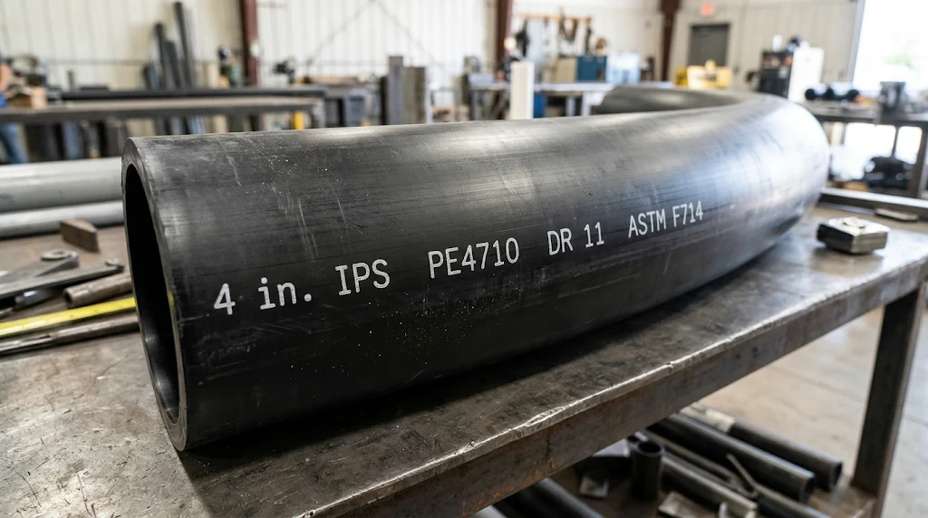
✓ Scopes checked against the AWWA standards list and the ASTM F714 description, November 2026Check the print line against the order and the specification, covering manufacturer, size and OD system, DR, material designation (such as PE4710), standard, and pressure class.
⭐ HDPE SDR Calculation Formulas
The core HDPE formulas are SDR = OD ÷ t, t = OD ÷ DR, ID ≈ OD – 2t, and PR = 2·HDS ÷ (DR – 1), which give 0.409 in. wall and 200 psi for 4 in. IPS DR 11 PE4710.
SDR
SDR = OD ÷ t_min
Wall Thickness
t_min = OD ÷ DR. For two sizes at the same OD: t1 ÷ t2 = DR2 ÷ DR1.
Inside Diameter
Idealized: ID = OD – 2t. PPI average estimate: ID_avg ≈ OD – 2.12 × OD ÷ DR. Flow area: A_f = π ID² ÷ 4.
Pressure Rating
PR = 2(HDS) ÷ (DR – 1) for OD-controlled pipe. Use a different equation for SIDR pipe.
Worked HDPE SDR Examples
Seven worked examples show SDR from dimensions, wall thickness, pressure rating, wall comparison, and the two inside-diameter methods.
SDR from dimensions
Use the manufacturer’s specified nominal dimensions, not an approximate field measurement.
Minimum wall of 8 in. IPS DR 17
Check the product standard’s rounding and minimum-wall requirements before using the rounded number for specification or purchasing.
Pressure rating of PE4710 DR 17
Matches the PPI standard rating. Surges, temperature, fittings, and external loads are separate.
Compare two wall thicknesses
This is a wall ratio, not a pressure ratio.
Average inside diameter of 6 in. IPS DR 11
Geometric ID with minimum wall is 6.625 – 2(0.6023) = 5.420 in. The 5.348 in. figure is a calculated estimate, not a certified finished inside diameter.
Idealized vs. PPI inside diameter, 4 in. IPS DR 11
The difference comes from using average wall (minimum plus 6%) instead of minimum wall.
Approximate flow area
Flow area is not flow rate. See the Pipe Flow Rate Chart for hydraulics.
How to Choose the Correct HDPE SDR
To choose an HDPE SDR, confirm the PE material and standard, find sustained and surge pressure, check temperature, compare pressure class and bore, and verify fittings and loads.
- Material and standard: PE4710 or other, ASTM F714, AWWA C901 or C906.
- Diameter system: IPS, DIPS, or metric.
- Pressure requirement: maximum sustained working pressure.
- Surges: recurring and occasional events.
- Temperature and fluid.
- Hydraulic requirement: verified average ID.
- External loads and installation method.
- Fitting compatibility and local requirements.
For a full selection walkthrough with a worked water-main example, see the How to Choose HDPE Pipe SDR guide. Pressure class alone does not finish the design. SDR is not a pipe schedule: do not read SDR 11 as Schedule 80 (see the Pipe Schedule Chart, Schedule 40 Pipe Chart, and Schedule 80 Pipe Chart), and PE differs from PEX and PVC (see the PEX Pipe Size Chart and PVC Pipe Size Chart).
⭐ Common HDPE SDR Mistakes
The most common HDPE SDR mistakes are treating SDR as a pressure rating, mixing IPS and DIPS, and calling a calculated inside diameter a manufacturer value.
Rating basis
- Using SDR as a pressure rating
- Assuming SDR 11 always means 200 psi
- Applying PE4710 ratings to another PE grade or to gas
- Ignoring temperature derating
- Using the water chart for chemical service
Dimensions
- Mixing IPS and DIPS outside diameters
- Calling OD – 2t a manufacturer-certified inside diameter
- Confusing minimum wall with average wall
- Rounding a minimum wall down and treating it as compliant
- Treating SDR as equivalent to a steel or PVC schedule
- Using SDR for SIDR pipe
System design
- Ignoring pressure surges
- Ignoring fittings and joint compatibility
- Using SDR alone for burial depth or bend radius
- Assuming a thicker pipe is always the better hydraulic choice
- Choosing only from stocked sizes
- Using outdated standards or editions
HDPE SDR FAQs
These are the most common questions about HDPE SDR, answered with PE4710 water reference values.
What does SDR mean in HDPE pipe?
SDR stands for standard dimension ratio, the pipe’s outside diameter divided by its specified minimum wall thickness. A lower SDR means a thicker wall at the same OD. It is a geometric ratio, so pressure capability also depends on the polyethylene material, temperature, and service conditions.
Is HDPE SDR 11 stronger than SDR 17?
At the same outside diameter and comparable material and conditions, SDR 11 has a thicker wall and a higher pressure rating, 200 psi versus 125 psi for PE4710 water at 73°F. Complete structural performance still needs checks of surges, external loads, joints, and installation.
What is the pressure rating of PE4710 SDR 11?
Under PPI’s standard PE4710 water reference conditions at 73°F with a 1,000 psi hydrostatic design stress, DR 11 corresponds to a 200 psi rating. It does not automatically apply to other materials, higher temperatures, gas service, or every manufacturer product.
What is the pressure rating of PE4710 SDR 17?
Under the same PE4710 water reference conditions, DR 17 corresponds to a 125 psi rating, calculated as 2 × 1,000 ÷ 16. Confirm the figure against the pipe marking, the governing standard, and manufacturer data before relying on it for a project.
How do you calculate HDPE SDR?
Divide the outside diameter by the specified minimum wall thickness. A pipe with a 6.625 in. OD and a 0.6023 in. minimum wall has an SDR of about 11. Use the manufacturer’s specified nominal dimensions, not an approximate field measurement, to determine the exact designation.
Is HDPE SDR the same as pipe schedule?
No. SDR is a ratio of diameter to minimum wall, while pipe schedule is a separate dimensional classification used for steel and PVC. HDPE pressure pipe is commonly specified by outside diameter and DR, and SDR 11 is not equivalent to Schedule 80.
Is SDR 11 the same as DR 11?
They are commonly used together for the same standardized geometry. DR is the general ratio of outside diameter to minimum wall, and SDR indicates a preferred standardized ratio. Keep the exact designation printed on the pipe or shown in the governing standard.
What is SIDR?
SIDR is the standardized inside-diameter ratio used for inside-diameter-controlled pipe, where the ratio is the inside diameter divided by the minimum wall. PPI gives a different pressure equation for it, so the OD-based formula 2 HDS ÷ (DR – 1) must not be used unchanged.
How do I calculate HDPE wall thickness from SDR?
Divide the outside diameter by the DR. A 4.500 in. OD at DR 11 gives 0.409 in., and 8.625 in. at DR 17 gives 0.507 in. Use the standard’s dimension table for rounding and tolerances, and never round a required minimum wall downward.
Does a lower SDR reduce inside diameter?
Yes, for the same outside diameter. A 4.500 in. pipe has an idealized inside diameter of 3.682 in. at DR 11 and 3.971 in. at DR 17. Manufacturers publish average IDs that run slightly smaller, so use those for flow calculations.
What is the difference between IPS and DIPS HDPE?
They are different outside-diameter series. A nominal 4 in. IPS pipe has a 4.500 in. OD, while a 4 in. DIPS pipe has a 4.800 in. OD. The same nominal size and DR therefore give different wall thickness, and fittings and fusion equipment must match the OD system.
Which standard covers large HDPE pressure pipe?
ASTM F714-25 covers OD-controlled PE pressure pipe in DIPS 3 and larger, IPS 4 and larger, and metric 90 mm and larger. For waterworks, AWWA C906-21 covers 4 to 65 in. pipe and C901-25 covers 3/4 to 3 in. water service pipe and tubing.
Does temperature change HDPE pressure rating?
Yes. PE pressure ratings vary with temperature, and the standard values are for 73°F, with AWWA PE4710 classes assuming service up to 80°F. At higher sustained temperatures a temperature factor from PPI or the manufacturer reduces the allowable pressure, so a 73°F rating must not be reused unchanged for warm service.
Are pressure surges included in HDPE pressure class?
AWWA PE4710 pressure class includes specified allowances for recurring surges, with total pressure limits of 1.5 times the class for recurring and 2.0 times for occasional surges. These are limits on total pressure, not extra pressure to add, and a transient analysis may still be required.
Can I use the PE4710 water chart for natural gas?
No. Gas piping design is regulated separately and uses its own design factors and pressure formulas, as in 49 CFR 192.121. The 125, 160, and 200 psi water ratings must not be read as natural gas service pressures, and gas systems follow their own standards and regulations.
How does HDPE DR affect bend radius?
Minimum cold bend radius is a multiple of OD that generally increases with DR, such as 20 × OD for DR 7 to 9 and 27 × OD for DR 17 to 21 in one PPI field manual. Other documents group differently, so match the source to the application.
Why is DR 7.3 not exactly 320 psi?
The formula gives 2 × 1,000 ÷ 6.3 = 317.5 psi, and manufacturers list 317 or 318 psi. PPI’s list of rounded standard ratings begins at 250 psi, so 317.5 is a calculated value. Check the manufacturer’s published rating for DR 7.3 products.
Can SDR alone determine burial depth?
No. Buried pipe performance depends on soil support, cover depth, external loads, groundwater, compaction, deflection, and buckling. A lower SDR adds ring stiffness but does not by itself set an acceptable burial depth, so follow PPI and AWWA design guidance.
Using the HDPE SDR Chart
This HDPE SDR chart shows how DR sets wall thickness and PE4710 water pressure rating at 73°F, with calculation methods and limits.
Treat SDR as pipe-wall geometry. The allowable pressure of an actual pipe depends on its material, standard, temperature, surge conditions, joints, and installation. Use the published manufacturer ID for flow work, keep IPS and DIPS separate, and confirm the adopted standard before ordering. For dimensions use the HDPE Pipe Size Chart; for general pressure ratings use the Pipe Pressure Rating Chart.
📄 Download HDPE SDR Chart PDF
Use your browser print function to save this page as a print-ready PDF for specification and submittal folders. Buttons and image placeholders are hidden when printing.
- SDR and PE4710 rating chart
- IPS wall thickness table
- IPS vs. DIPS comparison
- Inside-diameter methods
- Formulas and worked examples