EMT Conduit Fill Chart 2026 – Maximum Wires by Conduit Size
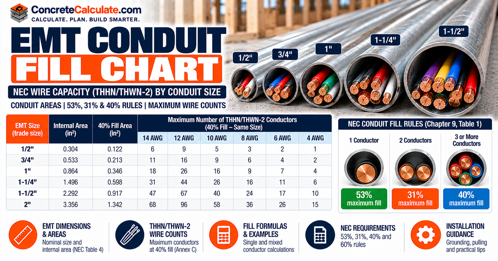
EMT Conduit Fill Chart
Maximum Wires by Conduit Size
See how many same-size THHN/THWN-2 conductors fit in 1/2 through 4 in. EMT, with EMT internal areas, the 53%, 31%, 40% and 60% limits, mixed-conductor calculations and clear limits on what fill does and does not tell you.
 Reviewed by Muhammad Ramzan Babar, PhD Researcher (Plasma Physics) & Calculator Developer – View Profile
Use the NEC Edition Your AHJ Adopted
NFPA lists the 2026 NEC as the current edition, but adoption varies by jurisdiction. The counts on this page are for same-size THHN/THWN/THWN-2 conductors in EMT only. Passing conduit fill does not establish ampacity compliance.
EMT Conduit Fill Chart: Maximum THHN Wire Capacity
Find how many same-size THHN/THWN-2 conductors fit in 1/2 through 2 in. EMT, then use the sections below for areas, mixed sizes and the rules behind the numbers.
How to Read the Chart
Find the conductor size in the left column and read across to your EMT trade size. For example, 1/2-in. EMT holds 9 conductors of 12 AWG THHN, 3/4-in. EMT holds 16, and 1-in. EMT holds 26. These counts apply only to same-size THHN/THWN/THWN-2 conductors in EMT, and only under the NEC edition your AHJ has adopted.
Maximum Same-Size THHN/THWN-2 Conductors
| THHN/THWN-2 | 1/2 in. | 3/4 in. | 1 in. | 1-1/4 in. | 1-1/2 in. | 2 in. |
|---|---|---|---|---|---|---|
| 14 AWG | 12 | 22 | 35 | 61 | 84 | 138 |
| 12 AWG | 9 | 16 | 26 | 45 | 61 | 101 |
| 10 AWG | 5 | 10 | 16 | 28 | 38 | 63 |
| 8 AWG | 3 | 6 | 9 | 16 | 22 | 36 |
| 6 AWG | 2* | 4 | 7 | 12 | 16 | 26 |
| 4 AWG | 1 | 2 | 4 | 7 | 10 | 16 |
| 3 AWG | 1 | 1 | 3 | 6 | 8 | 13 |
| 2 AWG | 1 | 1 | 3 | 5 | 7 | 11 |
| 1 AWG | 1 | 1 | 1 | 4 | 5 | 8 |
| 1/0 AWG | 1 | 1 | 1 | 3 | 4 | 7 |
| 2/0 AWG | None | 1 | 1 | 2 | 3 | 6 |
| 3/0 AWG | None | 1 | 1 | 1 | 3 | 5 |
| 4/0 AWG | None | 1 | 1 | 1 | 2 | 4 |
- EMT only.
- Specified THHN/THWN/THWN-2 construction only.
- Mixed conductor sizes require an area calculation.
- Verify the locally adopted NEC edition.
- Fill compliance does not establish ampacity compliance.
- * Two 6 AWG THHN conductors total 0.1014 in², which is more than 31% of a 1/2-in. EMT (0.094 in²). The count of 2 follows the Annex C-derived method with the Chapter 9 Note 7 rounding rule for same-size conductors, and some secondary charts list 1 instead. Confirm this cell in your adopted edition.
For rules that apply to every raceway type and for comparisons among EMT, PVC, IMC and RMC, see the Conduit Fill Chart. This page is the EMT-only reference.
EMT Internal Area and Maximum Fill Chart
Trade Size vs. Inside Diameter
Trade size is a nominal name. A 1/2-in. EMT has a 0.622 in. inside diameter, and its 0.304 in² internal area is what fill uses.
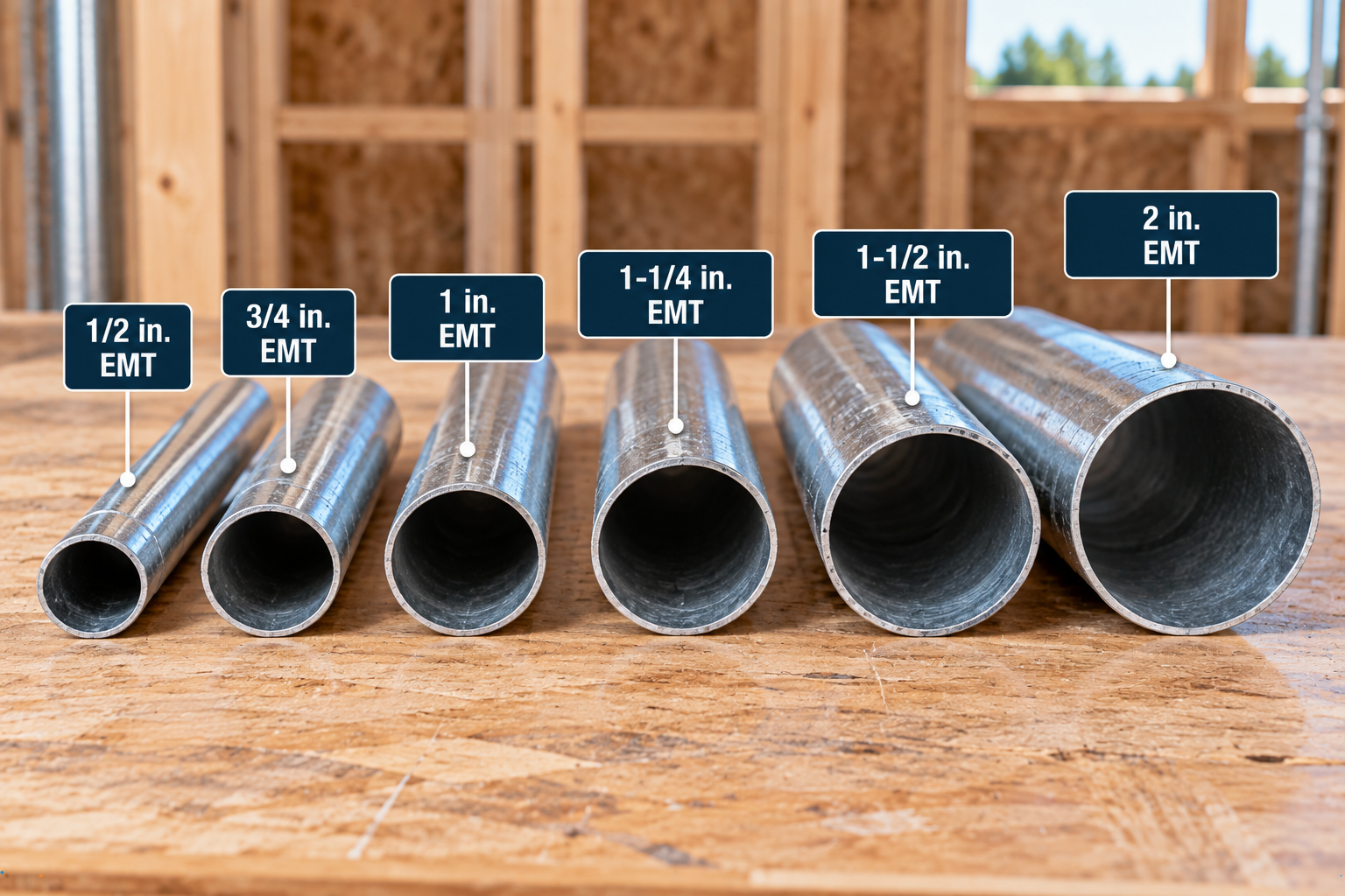
53%, 31%, 40% and 60% Areas
| Trade Size | Inside Diameter (in.) | Total Area (in²) | 53% (in²) | 31% (in²) | 40% (in²) | 60% Nipple (in²) |
|---|---|---|---|---|---|---|
| 1/2 in. | 0.622 | 0.304 | 0.161 | 0.094 | 0.122 | 0.182 |
| 3/4 in. | 0.824 | 0.533 | 0.282 | 0.165 | 0.213 | 0.320 |
| 1 in. | 1.049 | 0.864 | 0.458 | 0.268 | 0.346 | 0.518 |
| 1-1/4 in. | 1.380 | 1.496 | 0.793 | 0.464 | 0.598 | 0.898 |
| 1-1/2 in. | 1.610 | 2.036 | 1.079 | 0.631 | 0.814 | 1.222 |
| 2 in. | 2.067 | 3.356 | 1.779 | 1.040 | 1.342 | 2.014 |
| 2-1/2 in. | 2.731 | 5.858 | 3.105 | 1.816 | 2.343 | 3.515 |
| 3 in. | 3.356 | 8.846 | 4.688 | 2.742 | 3.538 | 5.308 |
| 3-1/2 in. | 3.834 | 11.545 | 6.119 | 3.579 | 4.618 | 6.927 |
| 4 in. | 4.334 | 14.753 | 7.819 | 4.573 | 5.901 | 8.852 |
What Is EMT Conduit?
Electrical metallic tubing (EMT) is a thin-wall metal raceway covered by NEC Article 358. It is different from intermediate metal conduit (IMC, Article 342), rigid metal conduit (RMC, Article 344) and PVC conduit (Article 352), and each has its own Table 4 dimensions. This page is limited to EMT, and the Conduit Fill Chart compares the raceway types.
NEC EMT Fill Rules: 53%, 31% and 40%
Chapter 9 Table 1 sets the maximum share of the EMT’s internal cross-sectional area that conductors may occupy.
| Number of Conductors | Maximum Fill | Allowed Area in 3/4-in. EMT (in²) |
|---|---|---|
| 1 | 53% | 0.282 |
| 2 | 31% | 0.165 |
| More than 2 | 40% | 0.213 |
One Conductor: 53%
A single conductor may occupy 53% of the EMT area.
Two Conductors: 31%
Exactly two conductors are limited to 31%, not 40%.
More Than Two: 40%
Three or more conductors may occupy 40% of the area. These percentages refer to cross-sectional area, not diameter.
EMT Conduit Fill Formula
Actual Fill Percentage
Maximum Allowable Area
Mixed Conductor Area
- A(conductors), A(total): combined area of all conductors and cables (in²)
- A(EMT): total internal EMT area from Table 4 (in²)
- N(i): quantity of conductors of type i
- A(i): area of one conductor of type i from Table 5 (in²)
- F: permitted fill written as a decimal
How to Calculate EMT Fill
- Identify the EMT trade size.
- Obtain the EMT internal area from Table 4.
- List every conductor.
- Identify the AWG or kcmil size and insulation type.
- Include grounding and bonding conductors.
- Obtain each conductor area from Table 5.
- Sum the occupied area.
- Apply the correct fill limit.
- Compare occupied and permitted area.
- Check ampacity separately.
| Conductor Size | Approx. Diameter (in.) | THHN/THWN-2 Area (in²) | Source |
|---|---|---|---|
| 14 AWG | 0.111 | 0.0097 | Chapter 9 Table 5 |
| 12 AWG | 0.130 | 0.0133 | Chapter 9 Table 5 |
| 10 AWG | 0.164 | 0.0211 | Chapter 9 Table 5 |
| 8 AWG | 0.216 | 0.0366 | Chapter 9 Table 5 |
| 6 AWG | 0.254 | 0.0507 | Chapter 9 Table 5 |
| 4 AWG | 0.324 | 0.0824 | Chapter 9 Table 5 |
| 3 AWG | 0.352 | 0.0973 | Chapter 9 Table 5 |
| 2 AWG | 0.384 | 0.1158 | Chapter 9 Table 5 |
| 1 AWG | 0.446 | 0.1562 | Chapter 9 Table 5 |
| 1/0 AWG | 0.486 | 0.1855 | Chapter 9 Table 5 |
| 2/0 AWG | 0.532 | 0.2223 | Chapter 9 Table 5 |
| 3/0 AWG | 0.584 | 0.2679 | Chapter 9 Table 5 |
| 4/0 AWG | 0.642 | 0.3237 | Chapter 9 Table 5 |
Worked EMT Fill Examples
Three 12 AWG THHN in 1/2″ EMT
Three 12 AWG THHN in 1/2-in. EMT
Practical interpretation: This checks physical fill only.
Mixed Conductor Sizes
Mixed Conductors in 1/2-in. EMT
Practical interpretation: No single Annex C row covers a mix of sizes, so the areas must be added.
NEC Annex C vs. Chapter 9
- Annex C: same-size conductor counts.
- Table 1: the permitted fill percentage.
- Table 4: the EMT raceway area.
- Table 5: the insulated conductor area.
- Compact-conductor data: Table 5A where compact conductors are used.
| Situation | Method |
|---|---|
| Same size and type conductors | Annex C EMT table |
| Mixed AWG sizes | Chapter 9 area calculation |
| Different insulation types | Individual conductor areas |
| Compact conductors | Applicable compact-conductor data (Table 5A) |
| Qualifying nipple of 24 in. or less | 60% provision (Table 1 Note 4) |
| Grounding conductor installed | Include its applicable area |
NEC Same-Size Conductor Rounding Rule
For same-size conductors, Chapter 9 Note 7 permits the next higher whole number when the calculation leaves a decimal of 0.8 or larger. It explains counts that would otherwise look one short.
That is the published 22 × 14 AWG THHN result. A second case is 6 AWG in 1-1/4-in. EMT: 0.5984 ÷ 0.0507 = 11.80, which rounds up to 12.
Same-Size Conductors Only
Do not extend this rounding shortcut to mixed conductor sets. For mixed sizes, add the actual areas and compare the total with the permitted area, with no rounding up of conductor counts.
1/2-Inch EMT Fill Chart
| Item | Value |
|---|---|
| Total area | 0.304 in² |
| 40% area | 0.122 in² |
| Inside diameter | 0.622 in. |
| 14 AWG THHN | 12 |
| 12 AWG THHN | 9 |
| 10 AWG THHN | 5 |
| 8 AWG THHN | 3 |
| 6 AWG THHN | 2 |
| 4 AWG THHN | 1 |
Two 6 AWG conductors carry the same asterisk noted under the main chart.
3/4-Inch EMT Fill Chart
| Item | Value |
|---|---|
| Total area | 0.533 in² |
| 40% area | 0.213 in² |
| Inside diameter | 0.824 in. |
| 14 AWG THHN | 22 |
| 12 AWG THHN | 16 |
| 10 AWG THHN | 10 |
| 8 AWG THHN | 6 |
| 6 AWG THHN | 4 |
| 4 AWG THHN | 2 |
See the main chart for additional sizes.
1-Inch EMT Fill Chart
| Item | Value |
|---|---|
| Total area | 0.864 in² |
| 40% area | 0.346 in² |
| Inside diameter | 1.049 in. |
| 14 AWG THHN | 35 |
| 12 AWG THHN | 26 |
| 10 AWG THHN | 16 |
| 8 AWG THHN | 9 |
| 6 AWG THHN | 7 |
| 4 AWG THHN | 4 |
Larger EMT Sizes: 1-1/4″ Through 4″
Larger sizes share one section. Counts are for same-size THHN/THWN/THWN-2 conductors.
| Trade Size | Inside Diameter (in.) | Total Area (in²) | 40% Area (in²) | 14 AWG | 12 AWG | 10 AWG | 8 AWG | 6 AWG | 4 AWG |
|---|---|---|---|---|---|---|---|---|---|
| 1-1/4 in. | 1.380 | 1.496 | 0.598 | 61 | 45 | 28 | 16 | 12 | 7 |
| 1-1/2 in. | 1.610 | 2.036 | 0.814 | 84 | 61 | 38 | 22 | 16 | 10 |
| 2 in. | 2.067 | 3.356 | 1.342 | 138 | 101 | 63 | 36 | 26 | 16 |
| 2-1/2 in. | 2.731 | 5.858 | 2.343 | 241 | 176 | 111 | 64 | 46 | 28 |
| 3 in. | 3.356 | 8.846 | 3.538 | 364 | 266 | 167 | 96 | 69 | 43 |
| 3-1/2 in. | 3.834 | 11.545 | 4.618 | 476 | 347 | 219 | 126 | 91 | 56 |
| 4 in. | 4.334 | 14.753 | 5.901 | 608 | 443 | 279 | 161 | 116 | 71 |
THHN, THWN-2, XHHW and Insulation Type
AWG identifies the conductor size but does not fix the overall insulated conductor area. The AWG dimensions themselves are in the Wire Gauge Chart. Do not apply THHN counts automatically to XHHW-2 or other constructions.
| AWG | THHN / THWN / THWN-2: dia (in.) / area (in²) | XHHW / XHHW-2: dia (in.) / area (in²) | THW / THHW: dia (in.) / area (in²) |
|---|---|---|---|
| 14 | 0.111 / 0.0097 | 0.133 / 0.0139 | 0.133 / 0.0139 |
| 12 | 0.130 / 0.0133 | 0.152 / 0.0181 | 0.152 / 0.0181 |
| 10 | 0.164 / 0.0211 | 0.176 / 0.0243 | 0.176 / 0.0243 |
| 8 | 0.216 / 0.0366 | 0.236 / 0.0437 | 0.236 / 0.0437 |
| 6 | 0.254 / 0.0507 | 0.274 / 0.0590 | 0.304 / 0.0726 |
| 4 | 0.324 / 0.0824 | 0.322 / 0.0814 | 0.352 / 0.0973 |
Because a 12 AWG XHHW conductor is 0.0181 in² against 0.0133 in² for THHN, fewer XHHW conductors fit in the same EMT.
Compact Conductors in EMT
Compact conductors are compressed so the voids between strands are virtually eliminated, which changes their overall dimensions and their occupied area. Choose the correct data: Table 5A for compact conductors instead of the standard Table 5 values. Standard conductor counts cannot automatically be transferred to compact conductors.
Grounding, Neutral and Spare Conductors
Grounding and Bonding Conductors
Installed equipment grounding and bonding conductors occupy physical raceway area and must be included in the fill calculation using their actual dimensions, whether insulated or bare (Chapter 9 Table 1 Note 3). Raceway fill is a different question from counting current-carrying conductors for ampacity adjustment.
Neutral and Spare Conductors
Any conductor physically installed in the EMT takes up area, whether it is a neutral or a spare, regardless of how other NEC calculations treat it. Whether a particular neutral counts as current-carrying for ampacity is a separate question that this page does not settle.
60% EMT Fill for Short Nipples
Chapter 9 Table 1 Note 4 allows a nipple not longer than 24 in. (600 mm) between boxes, cabinets and similar enclosures to be filled to 60% of its cross-sectional area. For 1/2-in. EMT: 0.304 × 0.60 = 0.1824 in².
| EMT Trade Size | 60% Nipple Area (in²) |
|---|---|
| 1/2 in. | 0.182 |
| 3/4 in. | 0.320 |
| 1 in. | 0.518 |
| 1-1/4 in. | 0.898 |
| 1-1/2 in. | 1.222 |
| 2 in. | 2.014 |
| 2-1/2 in. | 3.515 |
| 3 in. | 5.308 |
| 3-1/2 in. | 6.927 |
| 4 in. | 8.852 |
Not a General Short-Run Allowance
The 60% figure is not a general allowance for any short raceway. It applies only to a qualifying nipple, and the note also addresses ampacity adjustment for it. A normal run keeps the 53/31/40 limits.
EMT Fill vs. Ampacity Derating
| EMT Fill | Ampacity |
|---|---|
| Physical occupied area | Electrical current-carrying capability |
| Chapter 9 calculation | Separate NEC conductor rules |
| Determines raceway capacity | Determines allowable conductor loading |
A conduit can pass the fill check and still require ampacity adjustment for the number of current-carrying conductors.
EMT Fill vs. Pulling and Jamming
Maximum fill does not decide whether a pull is practical. Pull length, the number of bends, conductor outside diameter, pulling tension, sidewall pressure and jamming all matter. Southwire’s professional tools report fill and jam probability separately, which shows that they are distinct checks.
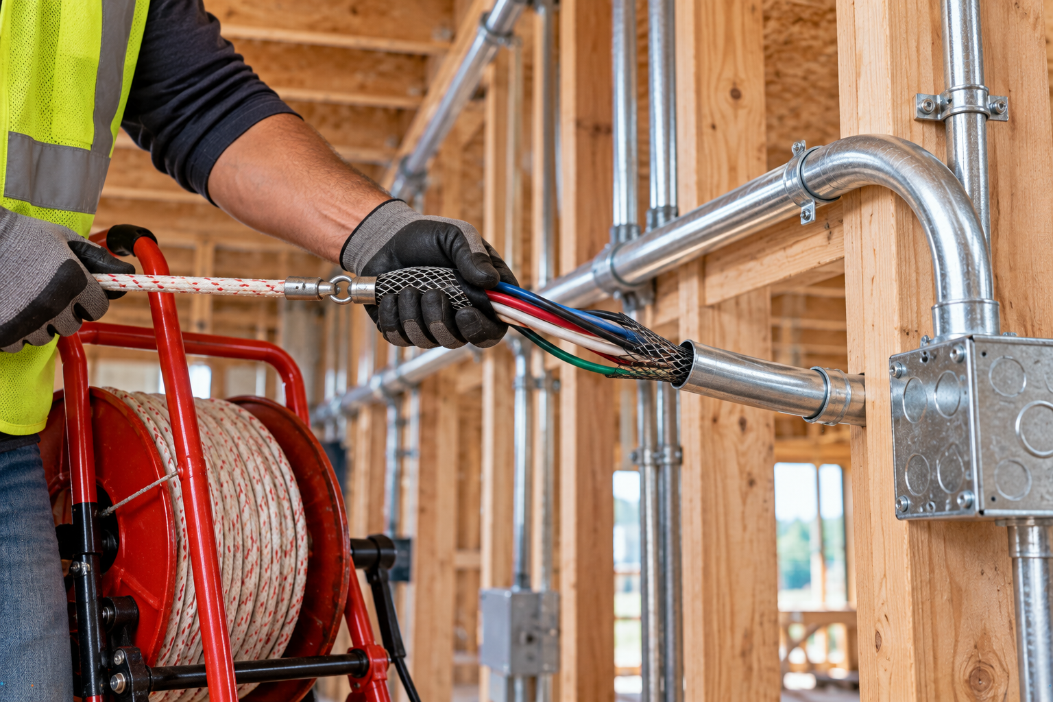
EMT Bends and Installation Considerations
Bends, pull points, fittings, support and avoiding damaged or deformed EMT all affect how well a run works. A crushed or kinked tube reduces the usable opening. Detailed bending and support requirements are outside this page’s scope.
EMT vs. PVC, IMC and RMC Fill
The same trade size does not have the same internal area across raceway types. For 3/4-in. raceways, Table 4 lists:
| Raceway Type | Total Area (in²) | 40% Area (in²) |
|---|---|---|
| EMT | 0.533 | 0.213 |
| IMC | 0.586 | 0.234 |
| RMC | 0.549 | 0.220 |
| PVC Schedule 40 | 0.508 | 0.203 |
| PVC Schedule 80 | 0.409 | 0.164 |
For the full comparison of EMT, PVC, IMC, RMC and other raceways, use the Conduit Fill Chart, and see the PVC Conduit Fill Chart for PVC.
How to Select the Correct EMT Size
- List the conductors.
- Identify the insulation and construction.
- Calculate the total occupied area.
- Determine the applicable fill percentage.
- Compare candidate EMT sizes.
- Select a compliant trade size.
- Check ampacity.
- Consider bends and pulling conditions.
- Verify the adopted NEC and AHJ requirements.
The smallest compliant EMT is not always the most practical installation choice.
EMT Fill Checker
The checker uses THHN/THWN/THWN-2 areas and a direct area comparison. Annex C may allow one more same-size conductor under the Note 7 rounding rule. Include grounding conductors, and use it for practice, not permit approval.
Common EMT Conduit Fill Mistakes
Assuming EMT is always limited to 40%
One conductor gets 53%, two get 31%.
Using trade size as the inside diameter
1/2-in. EMT is 0.622 in. inside.
Ignoring insulation type
THHN and XHHW areas differ.
Ignoring grounding conductors
They count toward fill.
Using THHN counts for XHHW
Use the actual conductor areas.
Using PVC or RMC dimensions for EMT
Table 4 areas differ by type.
Applying Annex C to mixed sizes
Add the actual areas instead.
Misusing the rounding provision
It applies to same-size conductors only.
Applying 60% to ordinary runs
It is for qualifying nipples only.
Assuming fill compliance means ampacity compliance
They are separate checks.
Ignoring the locally adopted NEC edition
The AHJ’s adopted edition governs.
EMT Conduit Fill Chart Limitations
What This Chart Does Not Establish
This page is an EMT-only fill reference. It does not by itself establish conductor ampacity, circuit conductor size, voltage drop, equipment grounding-conductor size, pulling tension, sidewall pressure, bend requirements, hazardous-location compliance, local amendment compliance or AHJ approval. The tables present a focused subset of NEC Chapter 9 data as published in recent editions, and some counts are calculated from them. Confirm every value against the edition your AHJ has adopted. See the Construction Charts hub for related references and the Engineering Calculators for calculation tools.
EMT Conduit Fill FAQs
How many 12 AWG wires fit in 1/2-in. EMT?
How many 12 AWG wires fit in 3/4-in. EMT?
How many 10 AWG wires fit in 1/2-in. EMT?
How many wires fit in 1-in. EMT?
Is EMT always limited to 40% fill?
Does the ground count toward EMT fill?
Can different wire sizes share EMT?
How do I calculate mixed wire sizes?
What is Annex C?
When can EMT use 60% fill?
Does insulation type affect fill?
Does passing EMT fill mean ampacity is acceptable?
Which NEC edition should I use?
Save the EMT Conduit Fill Chart as a PDF
Use your browser print function to save this reference for estimating folders, training binders and job planning.