Structural Bolt Size Chart 2026: Diameters, Hole Sizes & ASTM Grades
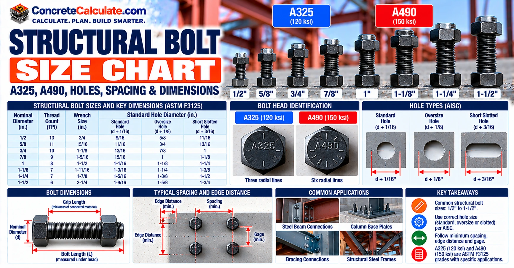
Structural Bolt Size Chart: Diameters, Hole Sizes & ASTM Grades
Structural bolt diameters from 1/2 to 1-1/2 in., standard holes, spacing and edge distance, A325, A490, F1852, F2280 and Grade 144, plus pretension and installation basics.
 Reviewed by Muhammad Ramzan Babar, PhD Researcher (Plasma Physics) & Calculator Developer. View Profile
Key Facts
- Structural bolt size is not just a diameter. A complete specification also needs the grade or group, length, style, hole type, installation condition and connection geometry.
- ASTM F3125 heavy-hex A325 and A490 bolts run from 1/2 to 1-1/2 in., while F1852, F2280 and Grade 144 run from 1/2 to 1-1/4 in.
- 3/4, 7/8 and 1 in. are the industry-standard diameters. Standard holes are 13/16, 15/16 and 1-1/16 in. for those sizes.
- Minimum spacing is 2⅔ bolt diameters and 3 diameters is preferred. Bolt size must come from connection design, not beam size. See the Bolt Grade Chart for general grades.
Structural Bolt Size Chart: Quick Reference
Diameters, standard holes and spacing for ASTM F3125 structural bolts from 1/2 to 1-1/2 in.
How to Read This Chart
Read across a row to see the bolt diameter, the standard fabricated hole, and the minimum and preferred center-to-center spacing. Highlighted rows (3/4, 7/8 and 1 in.) are the diameters AISC calls the industry standard for most steel connections. A grade name such as A325 is not a diameter.
| Nominal bolt diameter | Decimal diameter (in.) | Approx. metric equivalent | Standard hole diameter | AISC minimum spacing, 2⅔d | Preferred spacing, 3d |
|---|---|---|---|---|---|
| 1/2 in. | 0.500 | 12.7 mm | 9/16 in. | 1-1/3 in. | 1-1/2 in. |
| 5/8 in. | 0.625 | 15.9 mm | 11/16 in. | 1-2/3 in. | 1-7/8 in. |
| 3/4 in. | 0.750 | 19.0 mm | 13/16 in. | 2 in. | 2-1/4 in. |
| 7/8 in. | 0.875 | 22.2 mm | 15/16 in. | 2-1/3 in. | 2-5/8 in. |
| 1 in. | 1.000 | 25.4 mm | 1-1/16 in. | 2-2/3 in. | 3 in. |
| 1-1/8 in. | 1.125 | 28.6 mm | 1-3/16 in. | 3 in. | 3-3/8 in. |
| 1-1/4 in. | 1.250 | 31.8 mm | 1-5/16 in. | 3-1/3 in. | 3-3/4 in. |
| 1-3/8 in. | 1.375 | 34.9 mm | 1-7/16 in. | 3-2/3 in. | 4-1/8 in. |
| 1-1/2 in. | 1.500 | 38.1 mm | 1-9/16 in. | 4 in. | 4-1/2 in. |
Dimensional Guidance, Not Bolt Selection
This table is dimensional guidance, not a structural bolt-selection table. Required diameter must be established from connection design and all applicable limit states. Do not infer bolt diameter from beam size alone; it is verified through bolt strength, bearing, tearout, block shear, net section, spacing, edge distance, hole type and installation requirements.
Structural Bolt Diameter Chart
ASTM F3125 heavy-hex A325 and A490 bolts are furnished from 1/2 through 1-1/2 in., so the table covers the full inch range. Twist-off assemblies and Grade 144 stop at 1-1/4 in.
Standard Hole Size
A standard hole is 1/16 in. larger than the bolt diameter in every size shown. See the hole-size section below for oversize and slotted holes.
Minimum and Preferred Bolt Spacing
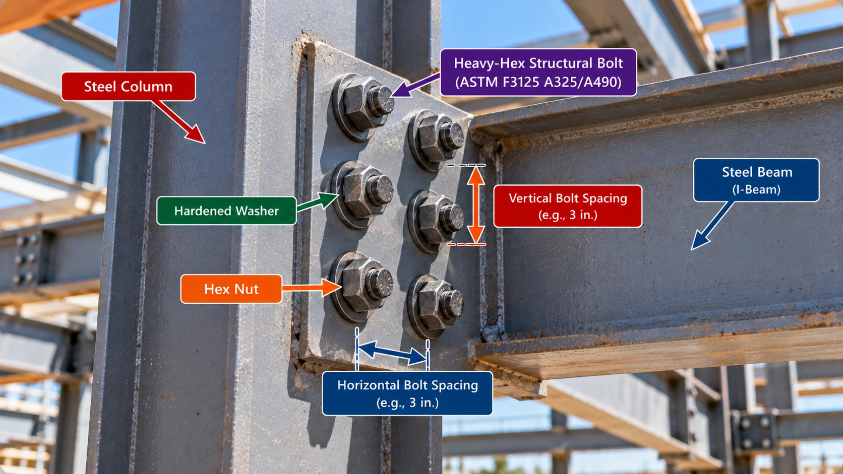
AISC sets the minimum center-to-center spacing at 2⅔ times the bolt diameter (about 2.67d) and prefers 3d where practical. The full discussion, with edge distance, is in the layout sections below.
Common Structural Bolt Diameters
AISC identifies 3/4-, 7/8- and 1-in. diameters as the industry-standard sizes with adequate design strength for the vast majority of steel-building connections, and notes that larger diameters can create tensioning and clearance difficulties. For general-purpose inch bolt dimensions, see the US Bolt Sizes Chart.
What Is a Structural Bolt?
High-strength fasteners made for steel-to-steel joints.
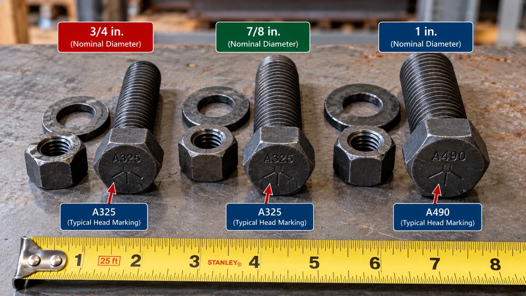
A structural bolt is a high-strength fastener made for structural-steel connections under the applicable ASTM, AISC and RCSC provisions. Its size, strength, head and nut geometry, and installation method are all controlled, so it is not the same as hardware-store bolts.
| Fastener | What it is | Typical use |
|---|---|---|
| Structural bolt | High-strength ASTM F3125 bolt with a heavy-hex head | Steel-to-steel structural joints |
| Ordinary or common bolt | Low-carbon bolt such as ASTM A307 | Light or secondary connections |
| Anchor rod | Rod or bolt cast into or post-installed in concrete | Anchoring base plates to foundations |
| Threaded rod | Fully threaded bar stock | Hangers, tie rods, general use |
| Machine bolt | General-purpose bolt, often regular hex | Machinery and light fabrication |
| Lag screw | Wood screw with bolt-style head | Fastening into wood |
Anchor Rods Are Different
An anchor bolt or anchor rod embedded in concrete is a different component from an F3125 structural joint bolt. See the Anchor Bolt Size Chart for anchorage, and the Bolt Grade Chart to compare general fastener grades with structural grades.
Bolt Diameter, Length and Grip Explained
Why a bolt length cannot be chosen from diameter alone.
Three dimensions describe how a structural bolt fits a joint, and they are not interchangeable.
| Term | Meaning | Why it matters |
|---|---|---|
| Diameter (d) | Nominal shank diameter | Sets area, hole size, spacing and edge distance |
| Length (L) | Length measured per the structural-bolt dimensional standard | Must reach through the plies, washer and nut with proper thread projection |
| Grip (G) | Combined thickness of the connected plies the bolt passes through | Drives the length choice, not the diameter |
🧮 General Length Concept
Variables: G = grip, Tn = nut thickness allowance, Tw = washer stack allowance, P = required thread projection or assembly allowance. There is no single universal addition, because head style, washer arrangement and thread length differ. Use the length tables in the project specification and the fastener standard.
ASTM F3125 Structural Bolt Sizes
One consolidated specification covers every current structural bolt grade.
ASTM F3125/F3125M is the current consolidated specification for high-strength structural bolts and assemblies. ASTM lists the F3125/F3125M-26 edition as active as of July 31, 2026. It replaced the separate standards A325, A325M, A490, A490M, F1852 and F2280, so older articles that cite those as standalone standards are out of date.
| Product | Style | Size range |
|---|---|---|
| Grades A325 and A490 | Heavy hex | 1/2 to 1-1/2 in. |
| Grades A325M and A490M | Heavy hex (metric) | M12 to M36 |
| Grades F1852 and F2280 | Twist-off assemblies | 1/2 to 1-1/4 in. |
| Grade 144 | Heavy hex and twist-off | 1/2 to 1-1/4 in. |
A325 Structural Bolt Size Chart
Grade A325 heavy-hex bolts: 120 ksi, 1/2 to 1-1/2 in.
Grade A325 heavy-hex bolts are furnished from 1/2 through 1-1/2 in. under F3125. A325 is a grade designation, not a diameter. Sizes such as 3/4 in. or 7/8 in. are diameters.
- Strength class: 120 ksi minimum tensile strength.
- Type: Type 1 (carbon or alloy steel) or Type 3 (weathering steel).
- Style: heavy hex head.
- Use: the most common choice for ordinary structural connections.
- Finish: plain finish unless the order specifies a coating. Coating and nut choices need to be coordinated.
| Property | Value |
|---|---|
| Standard | ASTM F3125/F3125M, Grade A325 |
| Style | Heavy hex |
| Size range | 1/2 to 1-1/2 in. |
| Minimum tensile class | 120 ksi |
| Strength group | Group 120 |
| Types | 1 or 3 |
A490 Structural Bolt Size Chart
Grade A490 heavy-hex bolts: 150 ksi class, 1/2 to 1-1/2 in.
Grade A490 heavy-hex bolts are also furnished from 1/2 through 1-1/2 in. They are in the 150 ksi class, with a higher tensile strength than A325. A490 should not replace A325 automatically just because more strength seems better.
- Pretension: a higher minimum pretension applies, so tension control and inspection matter more.
- Coatings: zinc galvanizing is generally not permitted on A490 because of hydrogen-embrittlement risk, so coating options differ from A325. Confirm in RCSC and the project specification.
- Installation: follow the RCSC installation requirements for the joint type.
- Mixing: do not mix A325 and A490 of the same diameter in one joint without considering quality control.
| Property | Value |
|---|---|
| Standard | ASTM F3125/F3125M, Grade A490 |
| Style | Heavy hex |
| Size range | 1/2 to 1-1/2 in. |
| Minimum tensile class | 150 ksi class |
| Strength group | Group 150 |
| Types | 1 or 3 |
F1852, F2280 and Grade 144 Bolt Sizes
Tension-control assemblies and the newer 144 ksi grade.
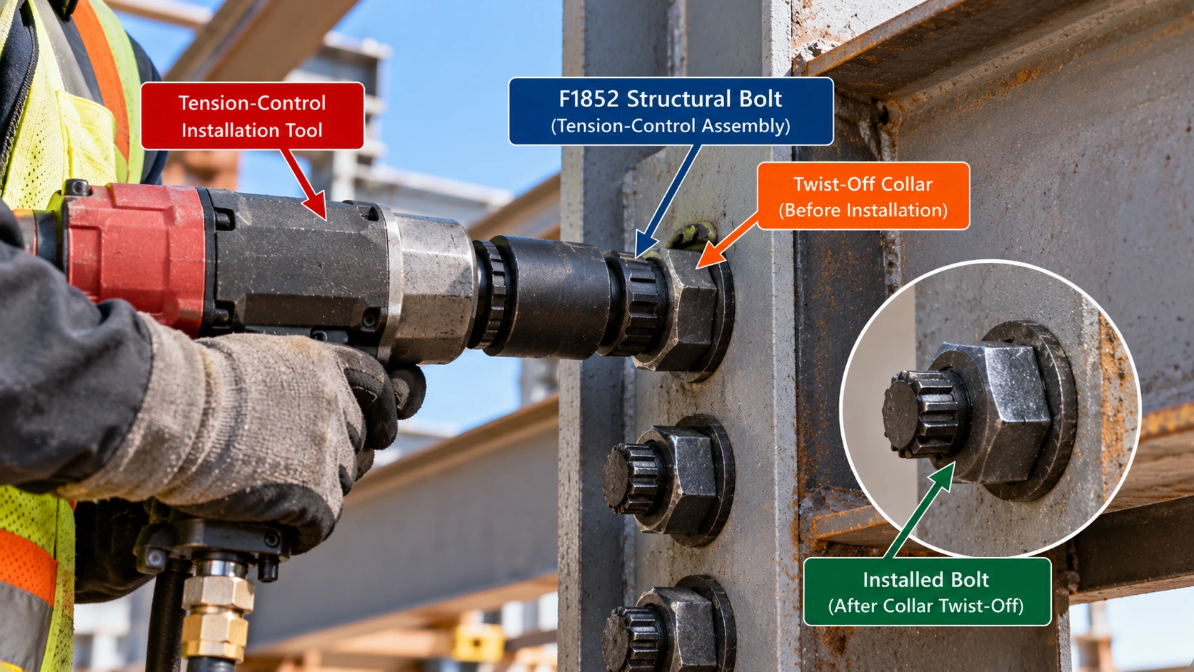
F1852 and F2280 are twist-off (tension-control) assemblies. They are furnished from 1/2 through 1-1/4 in. F1852 is the 120 ksi class counterpart to A325, and F2280 is the 150 ksi class counterpart to A490, but F1852 is not simply an A325 bolt: it is a separate assembly with a splined end that is twisted off at the required tension.
- Calibrated installation: the spline end shears off when the intended pretension is reached.
- Assembly: bolt, nut and washer are supplied and used as a set.
- Inspection: a visible, removed spline gives a field check, but inspection follows RCSC.
- Tool clearance: the installation tool needs room around the nut and the spline.
Grade 144 comes in both heavy-hex and twist-off styles through 1-1/4 in. It is covered in the next block of this section and again in the strength-group section.
| Grade | Strength class | Style | Size range |
|---|---|---|---|
| F1852 | 120 ksi class | Twist-off | 1/2 to 1-1/4 in. |
| F2280 | 150 ksi class | Twist-off | 1/2 to 1-1/4 in. |
| Grade 144 | 144 ksi class | Heavy hex and twist-off | 1/2 to 1-1/4 in. |
Grade 144 Structural Bolts
Many older bolt guides omit Grade 144. F3125-26 includes a 144 ksi inch-series grade in both heavy-hex and twist-off styles, furnished from 1/2 through 1-1/4 in. Its permitted use and installation follow the governing AISC and RCSC provisions, so check them before specifying it. In the 2025 RCSC table, Group 144 uses the same minimum pretension as Group 150.
Inch vs. Metric Structural Bolt Sizes
Two separate systems under one specification.
ASTM F3125 covers inch and SI (metric) products as separate standards, and they should not be mixed as exact equivalents. A325 and A490 are furnished in inch sizes from 1/2 to 1-1/2 in., while A325M and A490M are furnished from M12 to M36. Inch conversions below are for orientation only.
| Inch size | Approx. mm (converted) | Metric structural bolt note |
|---|---|---|
| 1/2 in. | 12.7 mm | |
| 5/8 in. | 15.9 mm | |
| 3/4 in. | 19.0 mm | M20 is not an interchangeable 3/4 in. bolt |
| 7/8 in. | 22.2 mm | |
| 1 in. | 25.4 mm | |
| 1-1/4 in. | 31.8 mm | |
| 1-1/2 in. | 38.1 mm |
Do Not Swap Inch and Metric
M20 is not simply a metric 3/4 in. structural bolt. Hole sizes, pretensions and strength rules differ, so use the inch or metric system as the project specifies. For general metric references, see the Metric Bolt Diameter Chart and the Bolt Diameter Chart.
Most Common Structural Bolt Diameters
3/4, 7/8 and 1 in. cover most steel-building connections.
AISC states that 3/4-, 7/8- and 1-in. diameters are the industry-standard sizes and provide adequate design strength for the vast majority of connections in steel structures. Larger diameters are permitted, but they can need larger clearances and edge distances, and they can be harder to tension.
Standardizing on a few diameters helps in several ways:
- Fabrication: fewer punches, drills and templates.
- Erection: fewer tools and sockets on site. See the Socket Size Chart for wrench sizes.
- Inspection: a limited set of sizes is easier to check.
- Inventory and cost: fewer SKUs and less risk of mix-ups.
| Diameter | Standard hole | Minimum spacing | Preferred spacing |
|---|---|---|---|
| 3/4 in. | 13/16 in. | 2 in. | 2-1/4 in. |
| 7/8 in. | 15/16 in. | 2-1/3 in. | 2-5/8 in. |
| 1 in. | 1-1/16 in. | 2-2/3 in. | 3 in. |
Structural Bolt Gross Area Chart
Gross shank area, thread tensile stress area, and why they differ.
Gross shank area is the circular area of the nominal diameter. It is used in several structural calculations, but it is not the same as thread tensile stress area, and it is not an allowable bolt strength.
Gross Area
🧮 Gross Shank Area
Variables: Ab = gross bolt area (in2), d = nominal diameter (in.). Example, 3/4 in. bolt: Ab = π (0.75)2 / 4 ≈ 0.442 in2.
| Diameter | Decimal diameter (in.) | Gross shank area Ab (in²) | Standard hole diameter |
|---|---|---|---|
| 1/2 in. | 0.500 | 0.196 | 9/16 in. |
| 5/8 in. | 0.625 | 0.307 | 11/16 in. |
| 3/4 in. | 0.750 | 0.442 | 13/16 in. |
| 7/8 in. | 0.875 | 0.601 | 15/16 in. |
| 1 in. | 1.000 | 0.785 | 1-1/16 in. |
| 1-1/8 in. | 1.125 | 0.994 | 1-3/16 in. |
| 1-1/4 in. | 1.250 | 1.227 | 1-5/16 in. |
| 1-3/8 in. | 1.375 | 1.485 | 1-7/16 in. |
| 1-1/2 in. | 1.500 | 1.767 | 1-9/16 in. |
Tensile Stress Area
Thread area is smaller than gross area. AISC 360-22 uses a tensile-stress-area approach in its updated bolt provisions, and AISC noted that the older approximate thread-area assumption becomes less accurate for larger bolts and threaded rods. The thread tensile stress area follows the ASME B1.1 formula below, using the standard coarse thread series (UNC) pitches for structural bolts.
🧮 Thread Tensile Stress Area
Variables: As = tensile stress area (in2), d = nominal diameter (in.), n = threads per inch.
| Diameter | Threads per inch (n) | Tensile stress area As (in²) | As / Ab |
|---|---|---|---|
| 1/2 in. | 13 | 0.1419 | 0.72 |
| 5/8 in. | 11 | 0.2260 | 0.74 |
| 3/4 in. | 10 | 0.3345 | 0.76 |
| 7/8 in. | 9 | 0.4617 | 0.77 |
| 1 in. | 8 | 0.6057 | 0.77 |
| 1-1/8 in. | 7 | 0.7633 | 0.77 |
| 1-1/4 in. | 7 | 0.9691 | 0.79 |
| 1-3/8 in. | 6 | 1.1549 | 0.78 |
| 1-1/2 in. | 6 | 1.4052 | 0.80 |
Do Not Equate Area With Strength
Do not equate gross area directly with allowable bolt strength. Strength comes from the applicable AISC provisions, which use the stress and area that match the limit state. Do not use gross area where the tensile area is required.
Structural Bolt Hole Size Chart
Standard, oversize and slotted holes from AISC Table J3.3.
AISC Table J3.3 lists nominal hole dimensions for four hole types. For bolts 1-1/8 in. and larger, the table gives formulas, so those rows below are calculated from the formulas. The same dimensions are used for fabrication and for engineering calculations, and they affect bearing, tearout, net section, block shear, slip resistance and installation.
| Bolt diameter | Standard hole | Oversize hole | Short slot (width × length) | Long slot (width × length) |
|---|---|---|---|---|
| 1/2 in. | 9/16 in. | 5/8 in. | 9/16 × 11/16 in. | 9/16 × 1-1/4 in. |
| 5/8 in. | 11/16 in. | 13/16 in. | 11/16 × 7/8 in. | 11/16 × 1-9/16 in. |
| 3/4 in. | 13/16 in. | 15/16 in. | 13/16 × 1 in. | 13/16 × 1-7/8 in. |
| 7/8 in. | 15/16 in. | 1-1/16 in. | 15/16 × 1-1/8 in. | 15/16 × 2-3/16 in. |
| 1 in. | 1-1/16 in. | 1-1/4 in. | 1-1/16 × 1-5/16 in. | 1-1/16 × 2-1/2 in. |
| 1-1/8 in. | 1-3/16 in. | 1-7/16 in. | 1-3/16 × 1-1/2 in. | 1-3/16 × 2-13/16 in. |
| 1-1/4 in. | 1-5/16 in. | 1-9/16 in. | 1-5/16 × 1-5/8 in. | 1-5/16 × 3-1/8 in. |
| 1-3/8 in. | 1-7/16 in. | 1-11/16 in. | 1-7/16 × 1-3/4 in. | 1-7/16 × 3-7/16 in. |
| 1-1/2 in. | 1-9/16 in. | 1-13/16 in. | 1-9/16 × 1-7/8 in. | 1-9/16 × 3-3/4 in. |
Standard Holes
The default condition. A standard hole is 1/16 in. larger than the bolt in the sizes in this chart.
Oversize Holes
Larger round holes used only where the connection type permits. They typically need hardened washers and have restricted use in bearing and slip-critical joints.
Short Slots
Allow limited adjustment in one direction, with slot direction mattering to the force path.
Long Slots
Allow greater movement and adjustment, and are more restricted in use. Installers may not enlarge holes freely in the field. Hole use depends on the connection type and the AISC and RCSC requirements. For general-purpose hole sizes, see the Bolt Hole Size Chart and the Clearance Hole Size Chart.
Minimum Structural Bolt Spacing
AISC 2⅔d minimum and 3d preferred.
AISC requires the center-to-center spacing of standard, oversize or slotted holes to be generally not less than 2⅔ times the nominal bolt diameter, and prefers 3 times the diameter where practical. AISC also requires adequate clear distance between holes.
🧮 Minimum and Preferred Spacing
Variables: s = center-to-center bolt spacing (in.), d = nominal bolt diameter (in.).
| Bolt | Minimum spacing | Preferred spacing |
|---|---|---|
| 3/4 in. | 2 in. | 2-1/4 in. |
| 7/8 in. | 2-1/3 in. (about 2.33 in.) | 2-5/8 in. |
| 1 in. | 2-2/3 in. (about 2.67 in.) | 3 in. |
Maximum Bolt Spacing
Why bolts can be too far apart as well as too close.
AISC also limits how far apart bolts can be, so the plates stay together and do not buckle or let moisture in between them. For painted members, or unpainted members not subject to corrosion, the maximum spacing is generally 24 times the thickness of the thinner connected part or 12 in. Closer limits apply for unpainted weathering steel. Compression members and staggered patterns have their own conditions.
Edge Distance Has Its Own Maximum
The maximum edge distance is generally 12 times the thickness of the connected part, but not more than 6 in. Do not present 6 in. as a universal maximum for every bolted joint, and do not confuse it with maximum spacing.
Structural Bolt Edge and End Distance
Table J3.4 minimums depend on diameter and edge condition.
Edge distance is measured from the center of a bolt hole to the nearest edge of the connected part. End distance is the same measurement in the direction of force. The required value depends on bolt diameter, hole type, edge condition (sheared versus rolled or thermally cut), force direction, and bearing and tearout checks. There is no universal “1.5d” rule.
| Bolt diameter | At sheared edges | At rolled edges of plates, shapes or bars, or thermally cut edges |
|---|---|---|
| 1/2 in. | 7/8 in. | 3/4 in. |
| 5/8 in. | 1-1/8 in. | 7/8 in. |
| 3/4 in. | 1-1/4 in. | 1 in. |
| 7/8 in. | 1-1/2 in. | 1-1/8 in. |
| 1 in. | 1-3/4 in. | 1-1/4 in. |
| 1-1/8 in. | 2 in. | 1-1/2 in. |
| 1-1/4 in. | 2-1/4 in. | 1-5/8 in. |
| Over 1-1/4 in. | 1-3/4 × d | 1-1/4 × d |
Lesser edge distances are permitted only where the applicable provisions of AISC Chapter J are satisfied, and AISC allows a small reduction at holes where the required strength is 25 percent or less of the maximum. Edge distances less than one bolt diameter are not permitted without approval from the engineer of record. For plate dimensions, see the Steel Plate Thickness Chart.
Pitch, Gage and Bolt Pattern Layout
Pitch, gage and edge distance, shown on a simple plate.
Fabrication drawings use a small set of layout terms. Knowing them makes bolt patterns easy to read.
| Term | Meaning |
|---|---|
| Pitch (s) | Center-to-center spacing of bolts along a line, usually in the direction of force |
| Gage (g) | Distance between adjacent lines of bolts, measured across the load line |
| Edge distance (e) | Center of hole to the nearest plate edge |
| End distance | Edge distance measured in the direction of force |
| Bolt-line spacing | Distance between parallel bolt lines |
Layout Check for a 3/4 in. Bolt
What it means: This checks geometry only. Bearing, tearout, net section and block shear still control the final layout. Beam and plate shapes are in the Steel I-Beam Chart and Structural Steel Shapes Chart.
Structural Bolt Length Selection
Grip, washers, nut and thread length decide the length.
Structural bolt length comes from the grip of the joint plus the nut, washers and required thread projection, not from the diameter. It also depends on bolt style, thread length and the project specification. ASME B18.2.6 gives the dimensional requirements for heavy-hex structural bolts, including length and thread length.
Grip
Grip is the combined thickness of the connected plies the bolt passes through. For washers, add each washer thickness in the length calculation. Adding more plies, a beveled washer or a DTI washer changes the length needed.
Thread Length
Standard heavy-hex structural bolts are partly threaded, so the shank and thread lengths vary with diameter and length. The thread must extend enough for the nut to seat with the required projection, and whether threads fall in the shear plane affects the available shear strength.
A325T Fully Threaded Bolts
F3125 Supplementary Requirement S1 allows A325 bolts with nominal lengths of four bolt diameters or less to be threaded full length, and they are marked A325T. For a 3/4 in. bolt that means up to 3 in. long, and for a 1 in. bolt up to 4 in. long. A490 has no equivalent A490T provision. Because the threads run through the whole bolt, they cannot then be excluded from the shear plane.
| Bolt diameter | Maximum A325T length (4 × d) |
|---|---|
| 3/4 in. | 3 in. |
| 7/8 in. | 3-1/2 in. |
| 1 in. | 4 in. |
Heavy-Hex Structural Bolt Head Dimensions
Wider than a regular hex bolt, so tool clearance matters.
Heavy-hex structural bolts have a wider head than ordinary hex bolts. ASME B18.2.6 sets the dimensions. Use it, not ordinary SAE hex-bolt tables, for structural bolts and for wrench and clearance checks.
| Bolt diameter | Heavy-hex width across flats | Regular hex bolt, for comparison |
|---|---|---|
| 1/2 in. | 7/8 in. | 3/4 in. |
| 5/8 in. | 1-1/16 in. | 15/16 in. |
| 3/4 in. | 1-1/4 in. | 1-1/8 in. |
| 7/8 in. | 1-7/16 in. | 1-5/16 in. |
| 1 in. | 1-5/8 in. | 1-1/2 in. |
| 1-1/8 in. | 1-13/16 in. | 1-11/16 in. |
| 1-1/4 in. | 2 in. | 1-7/8 in. |
| 1-3/8 in. | 2-3/16 in. | 2-1/16 in. |
| 1-1/2 in. | 2-3/8 in. | 2-1/4 in. |
The head height, bearing face and clearance for sockets and tension-control tools also come from ASME B18.2.6 and the tool maker. For tool sizes, see the Socket Size Chart.
Structural Bolt Nut Size Chart
Heavy-hex nuts that match the bolt grade.
High-strength bolting uses nuts made to ASTM A563/A563M or ASTM A194/A194M. For F3125 Grade A325 and A490, ASTM A563 Grade DH (or Grade DH3 for weathering-steel Type 3 assemblies) is the standard heavy-hex nut. Other A563 grades may be permitted for some plain A325 assemblies under RCSC, and galvanized assemblies need the correct nut and lubricant combination. Check the RCSC nut table for each bolt grade.
| Bolt | Typical compatible nut | Style | Check |
|---|---|---|---|
| A325 Type 1 | ASTM A563 Grade DH (other grades per RCSC) | Heavy hex | RCSC nut table |
| A325 Type 3 | ASTM A563 Grade DH3 | Heavy hex | Weathering assembly |
| A490 Type 1 | ASTM A563 Grade DH | Heavy hex | RCSC nut table |
| A490 Type 3 | ASTM A563 Grade DH3 | Heavy hex | Weathering assembly |
| F1852, F2280, Grade 144 | Per RCSC and the F3125 assembly | Heavy hex | Use the supplied assembly |
Heavy-hex nuts share the head width across flats shown above. For nut thickness, ASME B18.2.6 lists 39/64 in. for 5/8 in., 47/64 in. for 3/4 in. and 55/64 in. for 7/8 in. nuts. For general nut dimensions, see the Nut Size Chart.
Equipment for Your Project
Affiliate disclosure: As an Amazon Associate, ConcreteCalculate earns from qualifying purchases. We may also earn a commission from other affiliate links at no additional cost to you.
Structural Bolt Washer Size Chart
F436 hardened washers for structural joints.
ASTM F436/F436M governs hardened steel washers used with structural bolts. Washers are required at specific positions depending on the installation method and hole type. Oversize and slotted holes need hardened washers, and beveled or clipped washers and DTI washers have their own rules in RCSC.
| Bolt size (in.) | Inside diameter (in.) | Outside diameter (in.) | Thickness (in.) |
|---|---|---|---|
| 1/2 | 0.531 | 1.063 | 0.097 to 0.177 |
| 5/8 | 0.688 | 1.313 | 0.122 to 0.177 |
| 3/4 | 0.812 | 1.469 | 0.122 to 0.177 |
| 7/8 | 0.938 | 1.750 | 0.136 to 0.177 |
| 1 | 1.125 | 2.000 | 0.136 to 0.177 |
| 1-1/8 | See ASTM F436 | See ASTM F436 | See ASTM F436 |
| 1-1/4 | 1.375 | 2.500 | 0.136 to 0.177 |
| 1-3/8 | 1.531 | 2.750 | 0.136 to 0.177 |
| 1-1/2 | 1.625 | 3.000 | 0.136 to 0.177 |
For SAE, USS and other washer types, see the Washer Size Chart.
Structural Bolt Grades and Strength Groups
Group 120, Group 144 and Group 150.
AISC 360-22 moved away from the older Group A, B and C labels to strength-based group names: Group 120, Group 144 and Group 150. The names reflect minimum tensile strength classes in ksi.
| ASTM grade | Style | Strength group | Minimum tensile class | Size range |
|---|---|---|---|---|
| A325 | Heavy hex | Group 120 | 120 ksi | 1/2 to 1-1/2 in. |
| F1852 | Twist-off | Group 120 | 120 ksi | 1/2 to 1-1/4 in. |
| Grade 144 | Heavy hex and twist-off | Group 144 | 144 ksi | 1/2 to 1-1/4 in. |
| A490 | Heavy hex | Group 150 | 150 ksi class | 1/2 to 1-1/2 in. |
| F2280 | Twist-off | Group 150 | 150 ksi class | 1/2 to 1-1/4 in. |
Group 120
The A325 and F1852 class, with a 120 ksi minimum tensile strength.
Group 144
The newer Grade 144 class, 144 ksi, available as heavy hex and twist-off up to 1-1/4 in.
Group 150
The A490 and F2280 class, in the 150 ksi range. See the Bolt Grade Chart for a broader comparison with general-purpose bolt grades.
Structural Bolt Shear Strength
The basic relationship, and why it is only one check.
AISC defines the nominal shear strength of a bolt as the nominal shear stress times the gross bolt area. The stress depends on the bolt group and on whether threads are included in or excluded from the shear plane. Single shear counts one plane, and double shear counts two.
🧮 Nominal Bolt Shear Strength
Variables: Rn = nominal shear strength per shear plane (kips), Fnv = nominal shear stress from AISC Table J3.2 (ksi), Ab = gross bolt area (in2).
Conceptual Shear Example for a 3/4 in. A325 Bolt
What it means: This is a conceptual number for bolt shear only. It is not a universal allowable load from diameter alone. Bearing and tearout of the plate, block shear, net section, spacing and hole type can all control the connection first.
| Factor | Effect |
|---|---|
| Single or double shear | Number of shear planes carrying the load |
| Threads included or excluded | Changes the Fnv value |
| Bolt group | Group 120, 144 or 150 sets the stress level |
| Hole type | Affects bearing-type and slip-critical resistance |
| Joint type | Bearing-type or slip-critical design |
Structural Bolt Tension and Combined Loading
Tensile resistance, prying and interaction.
Bolt tension resistance depends on the group, the tensile area, the applied axial force, installation condition, combined shear and tension, and prying effects. The material tensile strength of the bolt is not the same as the available strength of the connection, because the connected parts, bolt layout and prying all reduce what the joint can carry.
Many structural bolts see shear and tension at the same time, as in moment connections, hangers and bracing. AISC Chapter J requires an interaction check for combined loading. Adding a shear capacity and a tension capacity together is not a valid calculation.
Bearing-Type vs. Slip-Critical Connections
Two design conditions with different load paths.
Structural joints work in one of two ways, and the choice is part of the design, not just the tightening method.
| Topic | Bearing-type | Slip-critical |
|---|---|---|
| Load transfer | Eventually through bolt bearing against the hole | Through friction at prepared faying surfaces under specified pretension |
| Pretension | Not always required | Required |
| Hole type | Standard, with limits for other types | Restrictions apply; check RCSC and AISC |
| Surface condition | Less critical | Faying surface class matters |
| Design basis | Bolt shear and bearing | Slip resistance, then bearing as a limit state |
Use the 2025 RCSC Specification as the principal high-strength bolting reference for both. Do not imply that either joint type is universally stronger.
Snug-Tight vs. Pretensioned Structural Bolts
Installation condition is a design decision.
Three installation conditions are commonly encountered, and they should not be confused.
- Snug-tight: the plies are brought into firm contact. AISC notes that snug-tight bolts are permitted in many bearing-type applications but not all.
- Pretensioned: the bolt is tightened to the specified minimum pretension by an approved RCSC method.
- Slip-critical: pretensioned, and designed to resist slip, with prepared faying surfaces.
Slip-critical is a connection design condition, not simply another tightening method.
When Structural Bolts Must Be Pretensioned
Pretension is required in the conditions set by RCSC, including certain connections subject to vibration or load reversal, certain built-up member conditions, and joints with high-strength tension or fatigue concerns. Do not reduce this to “A490 is always pretensioned.” Check the current RCSC and AISC provisions for the joint.
Structural Bolt Pretension Chart
Minimum pretension by diameter and strength group.
The table shows the specified minimum bolt pretension for pretensioned and slip-critical joints from the 2025 RCSC Specification (Table 5.2). Group 144 and Group 150 share one column. Older pretension charts, especially for diameters of 1-1/8 in. and larger, can differ, so do not use a legacy A325 or A490 chart without checking it against the 2025 RCSC edition.
| Diameter | Group 120 (A325, F1852), kips | Group 144 and Group 150 (Grade 144, A490, F2280), kips |
|---|---|---|
| 1/2 in. | 12 | 15 |
| 5/8 in. | 19 | 24 |
| 3/4 in. | 28 | 35 |
| 7/8 in. | 39 | 49 |
| 1 in. | 51 | 64 |
| 1-1/8 in. | 64 | 80 |
| 1-1/4 in. | 81 | 102 |
| 1-3/8 in. | 97 | 121 |
| 1-1/2 in. | 118 | 148 |
Pretension Is Not a Torque Value
These are bolt tension values, not wrench torques. Reach them with an RCSC-approved installation method, not a general torque chart.
Structural Bolt Installation Methods
Four RCSC-recognized ways to reach pretension.
RCSC recognizes controlled installation methods. Installation is a procedure, not a matter of tightening to a generic torque.
Turn-of-Nut
The nut is brought to snug-tight and then rotated a specified amount that depends on bolt length and joint geometry. Follow the RCSC table for the rotation.
Calibrated Wrench
A wrench is calibrated on a representative bolt assembly to reach the required pretension, with periodic checks.
Tension-Control Assemblies
F1852, F2280 and Grade 144 twist-off assemblies use a splined end that shears off at the calibrated tension. They need the proper installation tool and RCSC procedures.
Direct-Tension Indicators
Direct-tension indicator (DTI) washers show bolt tension by the closure of protrusions. They follow ASTM F959 and RCSC rules. Combined methods are allowed only where RCSC permits them.
Why Structural Bolts Do Not Use a Universal Torque Value
Torque depends on friction, so it cannot stand in for bolt tension.
A generic torque chart does not give the correct tension for a structural bolt. Torque depends heavily on lubrication, coating, thread condition, the nut factor, installation method, bolt reuse and storage or weather exposure. Two bolts tightened to the same torque can end up with very different tensions.
Structural high-strength bolts are therefore installed by an RCSC method that controls the bolt tension, not by looking up a torque value. The general references on the site are useful for ordinary fasteners, but they are not RCSC procedures. See the Bolt Torque Chart and the Bolt Torque Calculator for general-purpose torque references.
Do Not Use a Torque Chart for Pretension
Do not take a general torque table and tighten a structural bolt to that value to claim a pretensioned joint. Use the installation method required by RCSC and the project specification.
Structural Bolt Coatings, Types and Head Markings
Finish, material type and identification.
F3125 purchase orders must specify any coating or finish other than plain. Coatings affect the nut and bolt assembly, the lubricant, and slip-critical faying surfaces.
- Plain finish: the default if nothing else is specified.
- Galvanizing: allowed on A325 with the right nut and lubrication, but generally not allowed on A490 and other Group 150 bolts because of hydrogen-embrittlement risk. Confirm in RCSC.
- Approved coatings: only those accepted by RCSC for the grade.
- Weathering steel: Type 3 assemblies pair weathering bolts, nuts and washers.
Type 1 vs. Type 3
The type describes the material chemistry and corrosion-related product category, not the diameter. Type 3 is for weathering-steel applications where specified. It is not a “higher-strength A325.”
Identification and Head Markings
Inspectors identify the grade, the manufacturer and the style from head markings. Grade identification on heavy-hex bolts stays visible after installation. Ordinary SAE head markings are not proof of F3125 compliance.
A325/A490 vs. SAE, A307, A354 and A449 Bolts
Why a similar-looking bolt is not a substitute.
Several bolt standards look similar but are not interchangeable with F3125.
| Standard | What it is | Substitute for F3125? |
|---|---|---|
| SAE J429 Grade 5 / Grade 8 | Automotive-style bolts with similar strength to A325 / A490 | No. Dimensions, thread length and quality assurance differ |
| ASTM A307 | Low-strength carbon steel bolts | No, much lower strength |
| ASTM A449 | Heat-treated bolts for general use | In general no; dimensional and installation assumptions differ |
| ASTM A354 | Alloy-steel bolts, including larger sizes | Not automatically; engineering approval needed |
| ASTM F3125 | High-strength structural bolts and assemblies | The structural joint standard |
SAE Grade 5 and Grade 8 have strength levels equal to A325 and A490, but ASTM A325 and A490 specify thread length and head size and demand stricter quality assurance and inspection, so AISC does not treat them as acceptable substitutes. For general grade markings, see the Bolt Grade Chart.
Structural Bolts Larger Than 1-1/2 Inches
F3125 heavy-hex A325 and A490 structural bolts stop at 1-1/2 in. For larger diameters, engineers may use other externally threaded fasteners, such as ASTM A354, where appropriate for the design. Do not call every large threaded fastener an “A325 structural bolt.”
Structural Bolt Applications
Beams, columns, gussets and the difference from anchor rods.
Bolt size follows the connection design, not the member size. Do not publish or use a “beam size to bolt diameter” lookup unless it is tied to a specific engineered connection table.
Beam Connections
Shear tabs, double angles, end plates, beam seats and moment connections each use bolts differently. Bolt diameter depends on the shear, tension, number of bolts, plate thickness, hole type, edge distance and connection geometry. For members, see the Steel I-Beam Chart and Structural Steel Shapes Chart.
Column Connections
Column splices, base plates and heavy connection plates involve multiple limit states. Thicker or larger members do not automatically need larger bolts. See the HSS Size Chart for tube members and the Steel Plate Thickness Chart for plate dimensions.
Gussets and Bracing
Gusset plates and braces combine axial load, shear and block shear, and often tension, so each bolt group needs an engineered check. Welded alternatives are covered in the Fillet Weld Size Chart.
Structural Bolts vs. Anchor Rods
A structural bolt connects steel to steel. An anchor rod anchors a steel base plate to a concrete foundation. Do not use F3125 bolt dimensions as an anchor-rod sizing chart. See the Anchor Bolt Size Chart and Anchor Bolt Spacing Chart, and the Anchor Bolt Calculator and Base Plate Calculator.
How to Choose the Correct Structural Bolt Size
An engineering workflow, not a lookup.
A dimensional chart cannot perform all these engineering checks. Use this sequence as a framework and have the connection designed and reviewed.
- Identify the connection type.
- Determine the required factored or service forces.
- Select the bolt grade or group.
- Choose a preliminary bolt diameter.
- Check bolt shear.
- Check bolt tension.
- Check shear-tension interaction.
- Check bearing on the connected material.
- Check tearout.
- Check net-section rupture.
- Check block shear.
- Check minimum spacing.
- Check edge distance.
- Check the hole type.
- Check pretension and slip requirements.
- Check installation access and tool clearance.
- Check availability and tooling.
- Finalize bolt length, nut and washer arrangement.
Do Not Size by Beam Size
Do not infer required structural bolt diameter from beam size alone. Bolt diameter must be verified through connection design, including bolt strength, connected-material bearing, tearout, block shear, net section, spacing, edge distance, hole type and installation requirements.
Common Structural Bolt Size Mistakes
The errors that cause the most trouble with structural bolts.
Confusing grade and diameter
Assuming A325 means 3/4-in. diameter, or treating A325 and A490 as obsolete without mentioning F3125.
Using the wrong head and bolt
Using ordinary hex-bolt head dimensions for heavy-hex bolts, or using SAE Grade 8 instead of A490.
Hole mistakes
Assuming every structural bolt uses a hole 1/16 in. larger, ignoring oversize or slotted-hole rules, or using bolt diameter as hole diameter.
Thread and area errors
Ignoring threads in the shear plane, or using gross area as tensile thread area.
Bigger-is-better thinking
Assuming larger bolts always make stronger connections, or ignoring plate bearing, block shear and edge distance.
Layout errors
Confusing spacing with gage, or ignoring tool clearance for large bolts.
Using anchor-rod tables
Applying anchor-rod tables to structural joint bolts.
Torque misuse
Using generic torque charts for pretension, or using an outdated RCSC pretension table.
Mixing bolt grades
Mixing A325 and A490 bolts of the same diameter without quality-control considerations.
Inch and metric mix-ups
Assuming 3/4-in. and M20 are interchangeable.
Substituting fasteners
Using A354 or A449 without checking compatibility.
Reuse and joint type
Reusing bolts where prohibited, or treating slip-critical and snug-tight joints as equivalent.
Structural Bolt Size Chart Limitations
What this page does and does not establish.
This page provides a bolt dimensional reference, hole-size reference, spacing concepts, ASTM grade and style information, and introductory design relationships. It does not independently establish:
- Required bolt diameter or number of bolts.
- Connection capacity.
- Seismic qualification or fatigue performance.
- Slip-critical surface class.
- Pretension procedure or field repair method.
- Approved substitutions.
Final connection design must follow the applicable AISC, RCSC, ASTM and project requirements. Check the edition adopted for your project: AISC 360-22 is the current AISC specification and the 2025 RCSC Specification is the current high-strength bolting specification.
Structural Bolt Size FAQs
Straight answers to the questions people ask most about structural bolts.
What are standard structural bolt sizes?
ASTM F3125 heavy-hex A325 and A490 bolts are furnished from 1/2 to 1-1/2 in. Twist-off assemblies (F1852, F2280) and Grade 144 are furnished from 1/2 to 1-1/4 in. Metric A325M and A490M run from M12 to M36.
What is the most common structural bolt diameter?
AISC identifies 3/4, 7/8 and 1 in. as the industry-standard diameters for most structural-steel connections.
What sizes do A325 bolts come in?
Grade A325 heavy-hex bolts are furnished from 1/2 to 1-1/2 in. A325 is a grade, not a diameter.
What sizes do A490 bolts come in?
Grade A490 heavy-hex bolts are also furnished from 1/2 to 1-1/2 in.
What is ASTM F3125?
ASTM F3125/F3125M is the consolidated specification for high-strength structural bolts and assemblies. It covers Grades A325, A490, F1852, F2280, Grade 144 and the metric A325M and A490M.
Are A325 and A490 still valid designations?
Yes, as grades within ASTM F3125. The older standalone A325, A490, F1852 and F2280 standards were consolidated into F3125.
What is a Group 120 bolt?
Group 120 is the strength-based group for the 120 ksi class, which includes A325 and F1852.
What is a Group 150 bolt?
Group 150 is the strength-based group for the 150 ksi class, which includes A490 and F2280.
What is a Grade 144 structural bolt?
Grade 144 is a 144 ksi class in F3125, furnished from 1/2 to 1-1/4 in. in heavy-hex and twist-off styles. Check the governing AISC and RCSC provisions before specifying it.
What is the standard hole for a 3/4-in. bolt?
13/16 in., or 1/16 in. larger than the bolt, per AISC Table J3.3.
What size hole is used for a 7/8-in. structural bolt?
A standard hole is 15/16 in., per AISC Table J3.3.
What size hole is used for a 1-in. structural bolt?
A standard hole is 1-1/16 in., per AISC Table J3.3. The oversize hole is 1-1/4 in.
What is the minimum spacing for 3/4-in. bolts?
The AISC minimum center-to-center spacing is 2⅔d, or 2 in. for a 3/4 in. bolt. The preferred spacing is 3d, or 2-1/4 in.
What is the minimum spacing for 1-in. bolts?
The AISC minimum is 2⅔d, or about 2.67 in. for a 1 in. bolt. The preferred spacing is 3 in.
What is the minimum edge distance for structural bolts?
It depends on bolt diameter and edge condition. For a 3/4 in. bolt in a standard hole, AISC Table J3.4 gives 1-1/4 in. at sheared edges and 1 in. at rolled or thermally cut edges. Oversize and slotted holes add an increment.
What is the difference between bolt spacing and gage?
Spacing (pitch) is the center-to-center distance along a line of bolts. Gage is the distance between adjacent lines of bolts.
How is structural bolt length determined?
From the grip plus the nut, washers and required thread projection, according to the structural-bolt dimensional standard. It cannot be chosen from diameter alone.
What is bolt grip?
Grip is the combined thickness of the connected plies that the bolt passes through.
What does A325T mean?
A325T is a fully threaded A325 bolt permitted by the F3125 supplement for lengths up to four bolt diameters. Threads then cannot be excluded from the shear plane. A490 has no equivalent.
What is a tension-control bolt?
A tension-control bolt is a twist-off assembly (F1852, F2280 or Grade 144 twist-off) whose splined end shears off at the intended tension when installed with the proper tool.
What is the difference between F1852 and A325?
Both are in the 120 ksi class, but F1852 is a twist-off assembly with a splined end for tension control, up to 1-1/4 in., while A325 is a heavy-hex bolt up to 1-1/2 in.
Do structural bolts require washers?
Not always. RCSC requires hardened washers in specified cases, such as certain installation methods and oversize or slotted holes. Follow the RCSC specification and project requirements.
Can SAE Grade 8 replace A490?
No. AISC does not accept SAE J429 Grade 5 or Grade 8 as substitutes for A325 or A490, because dimensions, quality assurance and inspection requirements differ.
Can A449 replace A325?
Generally not. A449 and A354 are not automatic substitutes for F3125 structural bolts because their dimensional and installation assumptions differ.
Can structural bolts be galvanized?
A325 bolts can be galvanized with the correct nut and lubricant. A490 and other Group 150 bolts generally cannot be galvanized, so confirm RCSC and the project specification.
What is the difference between snug-tight and pretensioned?
Snug-tight means the plies are in firm contact. Pretensioned means the bolt is tightened to the specified minimum pretension by an approved method. Slip-critical is a design condition that requires pretension.
When is a slip-critical connection required?
When the connection design requires slip resistance, such as joints with load reversal or certain vibratory or fatigue conditions. The engineer of record specifies it.
Are structural bolts tightened by torque?
Not by a generic torque value. RCSC uses methods such as turn-of-nut, calibrated wrench, twist-off tension-control and direct-tension indicators. See the Bolt Torque Chart for general-purpose torque references.
Can a structural bolt be used as an anchor bolt?
No. An F3125 structural bolt joins steel to steel. Anchor rods that connect to concrete are a different component. See the Anchor Bolt Size Chart.
What bolts are used above 1-1/2 in. diameter?
F3125 A325 and A490 heavy-hex bolts stop at 1-1/2 in. For larger diameters, engineers may use other fastener standards such as ASTM A354 where appropriate.
Cite or Embed This Chart
📄 Print or Save This Chart as PDF
Use your browser’s print function to save the page as a PDF reference for jobsite binders and estimating folders.
Sources and Standards Used
Size ranges come from ASTM F3125/F3125M-26. Hole dimensions and edge distances follow AISC Tables J3.3 and J3.4, and pretension values follow the RCSC specification. Spacing, gross area, tensile stress area, head width and example strengths are calculated from the formulas shown and are marked as derived. Always confirm against the editions adopted for your project.
- ASTM F3125/F3125M-26, High Strength Structural Bolts and Assemblies
- AISC 360-22, Specification for Structural Steel Buildings
- RCSC, Specification for Structural Joints Using High-Strength Bolts (2025)
- AISC, Bolting FAQs
- ASME B18.2.6, Fasteners for Use in Structural Applications
- ASTM F436/F436M, Hardened Steel Washers