Stud Spacing Chart – Wall Framing, 2×4 and 2×6 Requirements
Stud Spacing Chart
Wall Framing, 2×4 and 2×6 Requirements
Use this U.S. wall-stud spacing reference to compare 12-, 16-, 19.2- and 24-inch modules, with qualified 2024 IRC guidance for wood stud size, wall height, loading, sheathing, bracing and layout.
 Reviewed by Muhammad Ramzan Babar, PhD Researcher (Plasma Physics) & Calculator Developer – View Profile
Important: Maximum Spacing Is Conditional
Sixteen inches on center is common, but it is not a universal requirement. A permitted spacing depends on the complete wall system: bearing status, stud size and grade, laterally unsupported height, supported roof and floors, sheathing, bracing, wind/seismic exposure, finishes, and local code. This page is a reference, not a substitute for approved plans or structural design.
Stud Spacing Chart – Quick Reference
Start here to identify the most common wall-stud spacing modules and the selected 2024 IRC Table R602.3(5) conditions that control common bearing and nonbearing walls.
How to Read This Chart
Spacing is measured centerline-to-centerline. The bearing-wall values below are prescriptive maximums only under the stated table conditions. They do not override requirements for lumber grade/species, lateral restraint, braced-wall design, sheathing, connections, wind, snow, seismic loads, local amendments, or engineered plans.
| Nominal Stud Size | Actual Size | Wall Type / Support Condition | Max. Laterally Unsupported Height | Max. Spacing | Primary Reference | Key Limitation |
|---|---|---|---|---|---|---|
| 2×3 | 1.5 x 2.5 in. | Nonbearing partition | 10 ft | 16 in. O.C. | IRC Table R602.3(5) | Not permitted for exterior walls under this table |
| 2×4 | 1.5 x 3.5 in. | Bearing wall: roof and ceiling only | 10 ft | 24 in. O.C. | IRC Table R602.3(5) | Qualified table conditions only |
| 2×4 | 1.5 x 3.5 in. | Bearing wall: one floor plus roof | 10 ft | 16 in. O.C. | IRC Table R602.3(5) | Not a roof-only wall |
| 2×4 | 1.5 x 3.5 in. | Nonbearing partition | 14 ft | 24 in. O.C. | IRC Table R602.3(5) | Partition conditions only |
| 2×6 | 1.5 x 5.5 in. | Bearing wall: roof and ceiling only | 10 ft | 24 in. O.C. | IRC Table R602.3(5) | Qualified table conditions only |
| 2×6 | 1.5 x 5.5 in. | Bearing wall: one floor plus roof | 10 ft | 24 in. O.C. | IRC Table R602.3(5) | Qualified table conditions only |
| 2×6 | 1.5 x 5.5 in. | Bearing wall: two floors plus roof | 10 ft | 16 in. O.C. | IRC Table R602.3(5) | More demanding lower-wall condition |
| 2×6 | 1.5 x 5.5 in. | Nonbearing partition | 20 ft | 24 in. O.C. | IRC Table R602.3(5) | Partition conditions only |
Standard Stud Spacing Quick Chart
| Spacing | Metric Equivalent | Typical Framing Context | Important Note |
|---|---|---|---|
| 12 in. O.C. | 305 mm | Closer framing where specified | Use only where the design, assembly or code calls for it |
| 16 in. O.C. | 406 mm | Conventional residential framing | Common, not automatically mandatory for every wall |
| 19.2 in. O.C. | 488 mm | Modular framing where approved | Requires deliberate layout and compatible materials |
| 24 in. O.C. | 610 mm | Qualifying conventional and advanced framing | Must satisfy the complete wall-system conditions |
Both 16- and 24-inch modules align with common 48-inch-wide panels: 16 inches divides 48 inches into three spaces, while 24 inches divides it into two spaces.
What Is Stud Spacing?
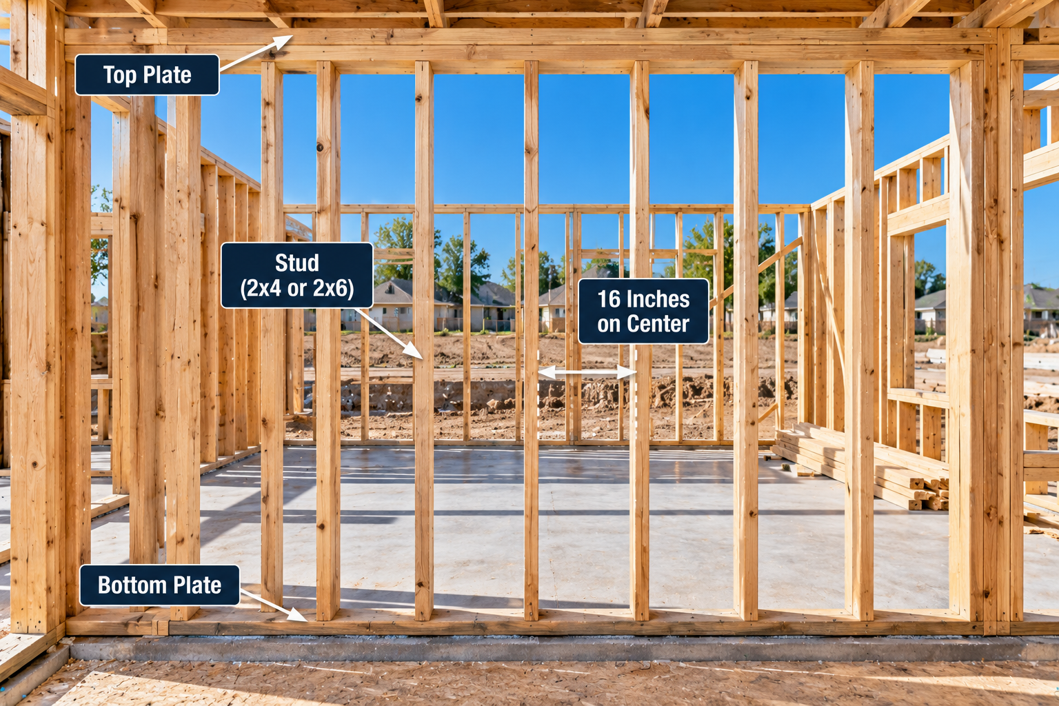
Stud spacing is the horizontal distance between the centerlines of consecutive vertical wood framing members. Plans normally state the center-to-center module because it coordinates structure, panels, finishes and layout marks.
- Structural load transfer: Spacing works with stud size, grade and height to carry roof, floor and wall loads.
- Wall stiffness: Stud spacing affects how the wall supports finishes and responds with its sheathing and bracing system.
- Panel support: Plywood, OSB, gypsum board and some claddings must have compatible framing support.
- Insulation cavities: Wider spacing changes the geometric clear cavity between framing members.
- Quantity and layout: The regular module is only the starting point. Openings, corners, intersections, headers and connections add framing.
What Does 16 Inches on Center Mean?
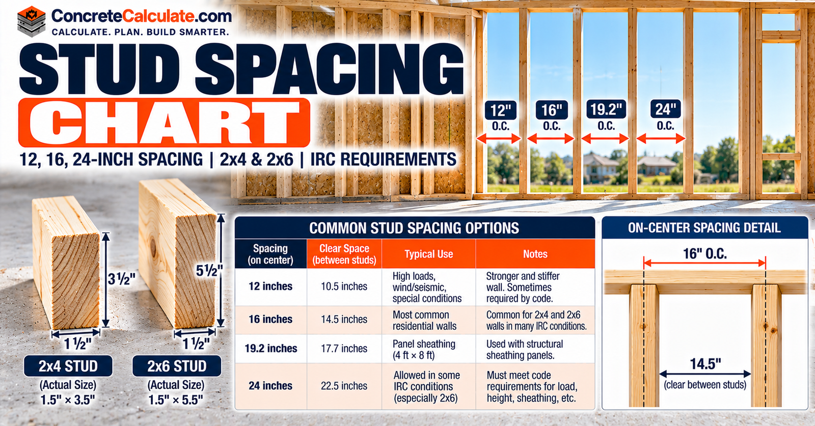
At 16 inches on center, the centerline of one stud is 16 inches from the centerline of the next. With standard 1.5-inch-thick studs, the nominal clear space is 16 – 1.5 = 14.5 inches before construction tolerances, blocking, services, insulation installation or other details. Sixteen inches equals approximately 406 mm.
Center-to-Center vs. Clear Stud Spacing
| On-Center Spacing | Stud Thickness | Nominal Clear Cavity | Metric O.C. Approx. |
|---|---|---|---|
| 12 in. | 1.5 in. | 10.5 in. | 305 mm |
| 16 in. | 1.5 in. | 14.5 in. | 406 mm |
| 19.2 in. | 1.5 in. | 17.7 in. | 488 mm |
| 24 in. | 1.5 in. | 22.5 in. | 610 mm |
Clear-cavity values are geometric calculations for nominal 1.5-inch-thick framing. They are not guaranteed finished cavity measurements.
Standard 12-, 16-, 19.2- and 24-Inch Stud Spacing
These are common framing modules, not interchangeable permissions. The structural and assembly requirements determine which module may be used.
12 in. O.C.
Closer spacing used where specified for a particular structural or finish requirement. It increases regular stud count and reduces the clear cavity width.
16 in. O.C.
A conventional residential module with broad compatibility for common wall assemblies. It remains subject to the applicable code and approved wall design.
19.2 in. O.C.
A modular layout sometimes used with compatible products and coordinated framing. It should not be substituted casually for 16- or 24-inch modules.
24 in. O.C.
Used in qualifying conventional and advanced framing. It needs compatible stud size, loading, height, sheathing, bracing, finishes and local-code conditions.
Sixteen-Inch vs. Twenty-Four-Inch Stud Spacing
Neither spacing should be selected independently of stud size, wall height, supported loads and the complete wall assembly.
| Factor | 16 in. O.C. | 24 in. O.C. |
|---|---|---|
| Regular stud count | More studs for the same straight wall length | Fewer regular studs for the same straight wall length |
| Structural use | Common conventional module | Must be qualified for size, loading, height and assembly |
| Wall stiffness | More closely spaced vertical supports | Depends more heavily on a compatible engineered or prescriptive wall system |
| Sheathing and drywall | Broadly common support spacing | Confirm panel, gypsum-board and fastening compatibility |
| Insulation geometry | Narrower clear cavities and more framing fraction | Wider clear cavities and lower regular-stud framing fraction |
| Layout | Three spaces per 48-inch panel width | Two spaces per 48-inch panel width |
Why 24-Inch Advanced Framing Is Different
DOE Building America guidance identifies 2×6 framing at 24 inches on center as a recognized advanced-framing approach when the entire wall system is designed and approved for it. It is not a blanket authorization to change any wall from 16 to 24 inches on center.
2024 IRC Stud Size, Height and Spacing Requirements
IRC Section R602.3.1 directs wood stud size, height and spacing to Table R602.3(5), subject to the table’s conditions and footnotes. The table distinguishes bearing and nonbearing walls, supported floors/roof, nominal stud size, laterally unsupported height and maximum spacing.
Code Table Conditions Matter
A table value is not a stand-alone design choice. Bearing walls require the required lateral support through sheathing or other approved bracing/bridging conditions. Wall bracing, wind, seismic design, openings, connectors and local amendments can impose additional requirements.
For tall exterior bearing walls, consult the applicable 2024 IRC R602.3.1 exceptions and the adopted code text. Those provisions use specified limits for wind, snow, tributary loading and other conditions. Where the prescriptive requirements do not apply, use an engineered wall design.
✓ Reference: 2024 IRC R602.3.1 and Table R602.3(5)Load-Bearing Wall Stud Spacing Chart
Selected common bearing-wall combinations from the 2024 IRC table. The values below are maximum spacings under the stated prescriptive conditions, not generic framing recommendations.
| Stud Size | Max. Wall Height | Roof and Ceiling Only | One Floor Plus Roof | Two Floors Plus Roof | Applicable Limitation |
|---|---|---|---|---|---|
| 2×4 | 10 ft | 24 in. O.C. | 16 in. O.C. | Not listed for this condition | Qualified IRC table conditions required |
| 2×6 | 10 ft | 24 in. O.C. | 24 in. O.C. | 16 in. O.C. | Qualified IRC table conditions required |
Non-Load-Bearing Wall Stud Spacing Chart
Interior partitions do not carry roof or floor gravity loads, but they still need compatible height, bracing, finish support and local-code conditions.
| Nominal Stud Size | Actual Depth | Maximum Laterally Unsupported Height | Maximum Spacing | Note |
|---|---|---|---|---|
| 2×3 | 2.5 in. | 10 ft | 16 in. O.C. | Not an exterior-wall table option |
| 2×4 | 3.5 in. | 14 ft | 24 in. O.C. | Ordinary nonbearing partition conditions |
| 2×6 | 5.5 in. | 20 ft | 24 in. O.C. | Ordinary nonbearing partition conditions |
Table R602.3(5) also contains entries for less-common 3×4 and 2×5 configurations. Use the adopted table directly when those members are proposed. IRC R602.5 also contains a separate limited provision for certain 2×3 interior nonbearing partitions at 24 inches on center; do not confuse that special partition provision with exterior or bearing-wall rules.
2×4 Stud Spacing Chart
A nominal 2×4 has an actual section of about 1.5 x 3.5 inches. Its permitted spacing changes materially with what the wall carries.
| 2×4 Wall Condition | Selected IRC Height Condition | Maximum Spacing | Practical Interpretation |
|---|---|---|---|
| Bearing: roof and ceiling only | 10 ft | 24 in. O.C. | A qualifying roof-only wall can differ from a floor-carrying wall |
| Bearing: one floor plus roof | 10 ft | 16 in. O.C. | Do not apply the roof-only allowance to this load condition |
| Nonbearing partition | 14 ft | 24 in. O.C. | Not a bearing-wall allowance |
For the habitable-attic conditions addressed in the IRC table footnotes, 2×4 limitations can be more restrictive. The specified 2×4-supported habitable-attic case is limited to a 32-foot roof span; larger spans require 2×6 studs or an engineered design under the applicable provisions.
For nominal and actual dimensions across lumber sizes, use the Lumber Size Chart.
2×6 Stud Spacing Chart
A nominal 2×6 has an actual section of about 1.5 x 5.5 inches. Its greater depth can allow a broader set of qualified prescriptive conditions, but it does not automatically authorize 24-inch spacing for every wall.
| 2×6 Wall Condition | Selected IRC Height Condition | Maximum Spacing | Key Context |
|---|---|---|---|
| Bearing: roof and ceiling only | 10 ft | 24 in. O.C. | Qualified table conditions |
| Bearing: one floor plus roof | 10 ft | 24 in. O.C. | Qualified table conditions |
| Bearing: two floors plus roof | 10 ft | 16 in. O.C. | Additional supported-floor loading changes the table limit |
| Nonbearing partition | 20 ft | 24 in. O.C. | Partition conditions only |
2×6 walls are often used for deeper insulation cavities, exterior-wall assemblies and qualifying advanced framing. Exterior insulation, moisture control, cladding support, wall bracing and finish compatibility remain part of the final wall design.
Stud Spacing by Wall Height
Laterally unsupported stud height is a core variable in prescriptive framing. Taller walls can require larger studs, closer spacing, intermediate lateral restraint, special IRC exceptions or engineering.
| Wall Height Range | What to Check | Typical Decision Path |
|---|---|---|
| 8-10 ft | Stud size, supported roof/floor load and table spacing | Use the applicable Table R602.3(5) row and notes |
| 11-12 ft | Height, exterior/bearing status, loading, wind and alternative provisions | Review the applicable R602.3.1 provisions and all qualifying conditions |
| Over 12 ft | Prescriptive limits, lateral restraint, wind/snow/tributary conditions | Use a specific qualifying exception only when all conditions are met, otherwise obtain engineering |
Tall-Wall Exception Is Not a General Allowance
One 2024 IRC exception permits qualifying No. 2-grade 2×6 roof-supporting studs up to 18 feet at 16 inches on center or 20 feet at 12 inches on center, subject to its listed ground-snow, wind-speed and tributary-length conditions. It should never be applied without checking the full adopted-code exception and the actual wall conditions.
Exterior vs. Interior and Multi-Story Walls
Exterior walls can carry gravity loads and resist wind while enclosing insulation and cladding. Interior bearing walls can support floors and roof loads. Nonbearing partitions have different table conditions. In multi-story homes, lower walls may support more floors, so a roof-only upper wall must not be used as the model for a lower wall carrying one or two additional floors.
For related horizontal members, see the Floor Joist Span Chart, Roof Rafter Span Chart and Ceiling Joist Span Chart.
Stud Spacing and Wall Sheathing Requirements
Gravity-load stud spacing does not automatically establish a compatible structural-sheathing or braced-wall system. Wood structural panel thickness, span rating, fastening, wind pressure, panel orientation, edge support and bracing method all matter.
| Sheathing / Bracing Factor | Why It Matters for Stud Spacing | What to Verify |
|---|---|---|
| Panel thickness | Thinner panels may have more restrictive support-spacing conditions | Applicable IRC wall-sheathing table and panel grade stamp |
| Span rating | Panel rating indicates permitted support-span use under listed conditions | Panel marking and wall application |
| Fastening schedule | Nail size and edge/field spacing affect wind-pressure and bracing performance | Code table, approved plans and local amendments |
| Braced-wall method | Some methods are limited to 16-inch spacing while others allow 24 inches under stated conditions | Braced-wall line, panel type, length and detailing |
| Wind and seismic design | Higher demand may change panels, fasteners, connections and framing layout | Design wind speed, exposure, seismic category and jurisdiction |
Under specified 2024 IRC Table R602.3(3) wind-pressure conditions, the 3/8-inch nominal wood-structural-panel entry is limited to 16-inch stud spacing, while certain 7/16-inch, 24/16-rated panel configurations allow up to 24 inches on center. The complete table condition, including fastening and wind criteria, controls.
Wall Bracing Is a Separate Check
Wall bracing provides lateral and shear resistance through braced wall lines and panels. A spacing allowed for gravity loads alone does not prove that the wall satisfies bracing, shear, wind or seismic requirements.
Keep roof-panel selection separate from wall sheathing. See the Roof Sheathing Thickness Chart for roof-specific panel guidance and the Nail Size Chart for fastener dimensions.
Equipment for Your Project
Affiliate disclosure: As an Amazon Associate, ConcreteCalculate earns from qualifying purchases. We may also earn a commission from other affiliate links at no additional cost to you.
Stud Spacing for Drywall, Interior Finishes and Exterior Cladding
Interior and exterior finishes need compatible backing and fastening support. A structural wall spacing is not automatically suitable for every gypsum board, siding or rated assembly.
| Finish or Cladding | Stud-Spacing Consideration | Verify Before Installation |
|---|---|---|
| 1/2-in. gypsum board | Compatibility can vary by orientation and manufacturer system | Manufacturer installation instructions and applicable code |
| 5/8-in. gypsum board | Often used where increased stiffness or rated assemblies are required | Specified assembly and fastener schedule |
| Fire-resistance-rated wall | Member spacing and board layers are assembly-specific | Approved tested/listed assembly |
| Wood, fiber-cement or vinyl siding | Direct support spacing can be manufacturer-specific | Cladding instructions, sheathing and furring requirements |
| Masonry veneer | Support, ties and drainage details are separate from regular stud module | Approved wall assembly and code provisions |
Use the applicable IRC Chapter 7 provisions and the relevant manufacturer instructions for gypsum board and cladding. Confirm drywall fasteners with the Drywall Screw Size Chart and framing fasteners with the Wood Screw Size Chart.
Advanced Framing at 24 Inches on Center
Advanced framing is an integrated strategy, not simply a wider stud-spacing choice. A common approach uses qualifying 2×6 walls at 24 inches on center with coordinated framing, aligned members and insulation-friendly corner/opening details.
- 2×6 studs can provide a deeper cavity than 2×4 walls.
- 24-inch modular framing can reduce the number of regular studs in an equal wall length.
- Aligned framing can create a more direct load path where the structural design permits it.
- Fewer regular studs can reduce framing fraction and thermal bridging, while whole-wall performance still depends on the full assembly.
- Headers, corners, intersections, opening details, sheathing, bracing and attachments must still meet the approved design.
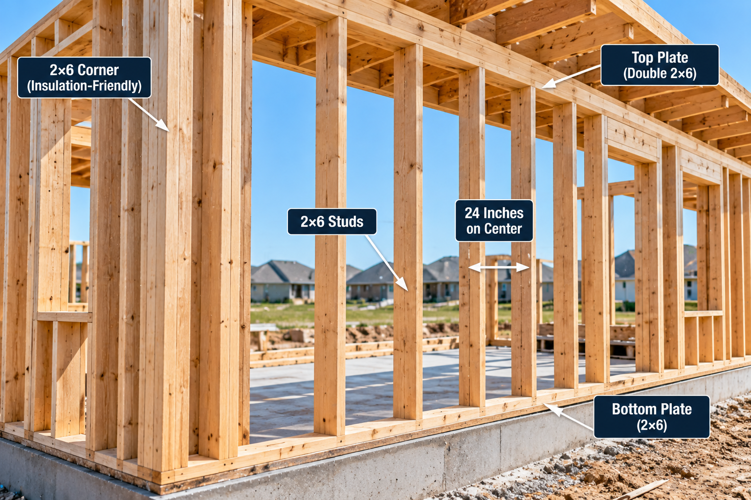
DOE Building America guidance treats this as a qualifying approach that still requires compliance with applicable structural and local requirements. For framing quantity planning, use the Framing Calculator.
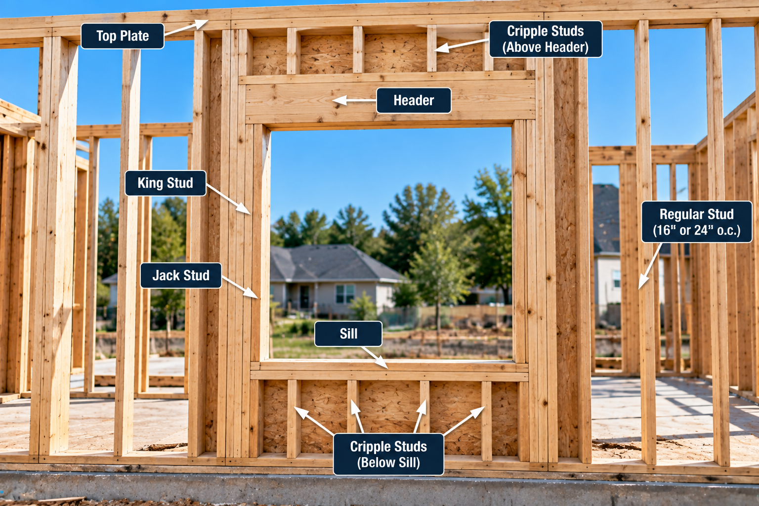
Stud Spacing Around Doors, Windows and Corners
Regular stud spacing does not eliminate additional framing around openings, corners and wall intersections. Openings create localized load transfer, attachment and finish-support requirements.
| Component | Function | Why It Is Not Counted as a Regular-Spacing Stud |
|---|---|---|
| King stud | Full-height member beside an opening | Located by the rough opening and header detail |
| Jack or trimmer stud | Supports the header ends | Added for load transfer, not simply the spacing module |
| Header | Transfers load across the opening | Must be sized for span and loads |
| Cripple stud | Frames above/below openings and supports finishes | Locations depend on layout and opening detail |
| Corner/intersection studs | Provide structural connection, sheathing and finish backing | Detail varies between conventional and advanced framing |
For header-specific span design, use the Header Span Chart and the Door Header Size Calculator.
Stud Spacing and Drilling or Notching Limits
Notching and boring rules protect the capacity of individual studs. They do not establish allowable stud spacing by themselves.
| Condition | Ordinary IRC Limit | Additional Requirement |
|---|---|---|
| Notch in exterior wall or bearing partition stud | Not more than 25% of stud depth | Follow IRC R602.6 and approved plans |
| Notch in nonbearing partition stud | Not more than 40% of stud depth | Follow IRC R602.6 and approved plans |
| Bored hole in stud | Up to 60% of stud depth under ordinary provisions | Maintain required edge clearance |
| Large hole in bearing/exterior stud | Additional requirements apply when hole exceeds 40% of stud depth | Check code provisions, reinforcement and protection details |
Keep required edge clearance and use protective nail plates where plumbing, electrical or mechanical work is close to the stud face. Confirm the full adopted IRC R602.6 text before cutting framing.
How to Lay Out Wall Studs Correctly
Use a deliberate plate-layout process instead of simply marking repeated measurements.
- Establish the wall length, direction, opening locations and structural drawings.
- Identify the approved spacing module and verify whether the wall is bearing or nonbearing.
- Mark stud centerlines and account for the actual 1.5-inch stud thickness.
- For a 16-inch module, use the carpenter’s layout convention so the first stud centerline aligns with the intended module. Where appropriate, offset the initial edge mark by half the stud thickness.
- Coordinate panel edges, blocking, braced wall panels and fastening requirements before framing.
- Lay out king studs, jack studs, headers, sills and cripple studs around every opening.
- Add required corner and partition-intersection backing while preserving insulation and finish requirements.
- Verify top-plate/bottom-plate alignment, connections, local code and approved plans before assembly.
On-Center Layout Is Not Edge-to-Edge Measurement
Marking an on-center module from the wrong stud face shifts the entire wall layout. Work from designated layout marks and verify actual member thickness and panel-edge support.
Stud Count Chart by Wall Length
For a straight wall with regular studs at both ends, use the conceptual estimate below before adjusting for openings, corners, intersections, braced panels, backing and other added framing.
Stud Spacing and Stud Count Calculator
Formula
Nregular = ceil((12L) / S) + 1, where L is wall length in feet and S is maximum spacing in inches. The result is a regular-position estimate only and is not a complete framing takeoff.
| Wall Length | 16 in. O.C. | 24 in. O.C. |
|---|---|---|
| 8 ft | 7 | 5 |
| 12 ft | 10 | 7 |
| 16 ft | 13 | 9 |
| 20 ft | 16 | 11 |
| 24 ft | 19 | 13 |
Counts assume regular positions, a stud at each end, and no openings or extra framing. For 19.2-inch spacing, actual layout and panel coordination require special attention.
Stud Spacing and Framing Material Estimates
Spacing affects regular stud quantity, but it is only one part of a framing estimate. Stock lengths, plates, headers, openings, blocking, waste, connectors, sheathing and labor all influence final cost.
20-Foot Straight Wall: 16 vs. 24 Inches on Center
Use the Lumber Calculator for quantity planning and the Board Foot Calculator for lumber-volume conversions.
How to Choose the Correct Stud Spacing
Follow this order before choosing a framing module:
- Identify the locally adopted building code and project jurisdiction.
- Determine whether the wall is exterior/interior and bearing/nonbearing.
- Identify the roof and floor loads transferred through the wall.
- Determine laterally unsupported wall height and required lateral support.
- Identify the actual stud size, lumber grade and species.
- Use the applicable IRC stud table, including all footnotes and exceptions.
- Check braced-wall, sheathing, fastening, wind and seismic conditions.
- Verify drywall, cladding, fire-rated and manufacturer assembly requirements.
- Evaluate advanced framing only when the complete assembly qualifies.
- Follow approved structural drawings or engineering when prescriptive rules do not apply.
For wind-demand context, see the Wind Load Calculator.
Common Stud Spacing Mistakes
These errors can turn a familiar framing module into an incorrect wall assembly.
Treating 16 inches as mandatory for every wall
It is common, but permitted spacing must follow the applicable wall conditions and approved design.
Assuming every 2×4 can be 24 inches on center
A 2×4 roof-only bearing wall and a 2×4 wall supporting a floor plus roof have different table limits.
Using partition limits for a bearing wall
Nonbearing-wall allowances do not establish spacing for a wall carrying roof or floor loads.
Ignoring wall height and lateral restraint
Taller walls can require different studs, closer spacing, special conditions or engineering.
Ignoring sheathing and wall bracing
Gravity-load spacing does not complete wind, seismic or braced-wall design.
Counting only regular studs
Openings, corners, intersections, headers and backing require additional framing.
Cutting large holes without checking limits
Notches and bored holes can reduce stud capacity and are limited by IRC R602.6.
Calling any 24-inch wall advanced framing
Advanced framing is a coordinated structural and energy-detailing system, not a spacing number alone.
Stud Spacing Chart Limitations
This chart addresses wood wall studs under stated 2024 IRC-style prescriptive conditions. The applicable maximum spacing can change with local amendments, wall height, roof/floor loading, stud grade/species, bracing, sheathing, fire-rated construction, wind/seismic design, openings, architectural layout and engineered wall systems.
Wood Studs Only
Steel studs use separate materials, design standards and manufacturer data. Do not select steel-stud spacing from these wood-stud charts. Always follow the approved project documents and jurisdiction requirements.
Stud Spacing FAQs
Download Stud Spacing Chart PDF
Use your browser print function to save this updated wall-framing reference as a PDF for jobsite binders, estimating folders and training materials.