Metal Roof Panel Span Chart 2026 – Support Spacing & Allowable Load Reference
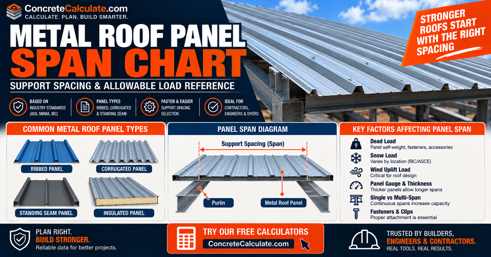
Metal Roof Panel Span Chart
Support Spacing & Allowable Load Reference
Panel type examples, single versus multi-span capacity, gauge versus actual base-metal thickness, and wind-uplift guidance on how far a metal roof panel can span between purlins, joists, or solid decking.
 Reviewed by Muhammad Ramzan Babar, PhD Researcher (Plasma Physics) & Calculator Developer, View Profile
There is no universal maximum metal roof panel span
Actual span depends on the exact panel product and system. MBCI’s PBU roof panel publishes spans from 3 to 9 ft for 29, 26, 24, and 22 gauge, with separate negative wind and live-load/deflection capacities for 1, 2, 3, and 4-span conditions. MBCI’s corrugated panel table gives values from 2 to 5 ft. These examples prove why the exact panel load table matters more than a generic “gauge equals span” assumption.
Metal Roof Panel Span Chart, Quick Reference
These are reference examples with explicit conditions, not a universal maximum-span-by-gauge table.
Metal Roof Panel Span Reference
| Panel Type | Attachment | Typical Support Condition | Common Tested Span Range* | Main Governing Check |
|---|---|---|---|---|
| Corrugated panel | Exposed fastener | Open framing | Product-specific (example: 2-5 ft) | Live load / uplift |
| R/PBR/PBU-type panel | Exposed fastener | Open framing | Product-specific (example: 3-9 ft) | Load + fastener pullout |
| Standing seam | Concealed clips | Open framing or deck | Product-specific | Panel/clip uplift |
| Structural standing seam | Concealed clips | Purlins/joists | Product-specific | Tested structural system |
| Architectural standing seam | Usually solid deck | Solid substrate | Not open-span reference | Deck/support system |
| Insulated roof panel | Concealed/exposed system | Framing | Product-specific | Panel skin/core + connection |
*Use actual manufacturer span tables for final design values. Example ranges shown are drawn from specific MBCI product lines, not a generic industry average.
Span ranges shown on this page are examples only. The allowable span for design must come from the exact panel manufacturer’s tested/load table and the project loads.
Panel Types and Support Conditions
Different metal roof panel families are built for different support strategies.
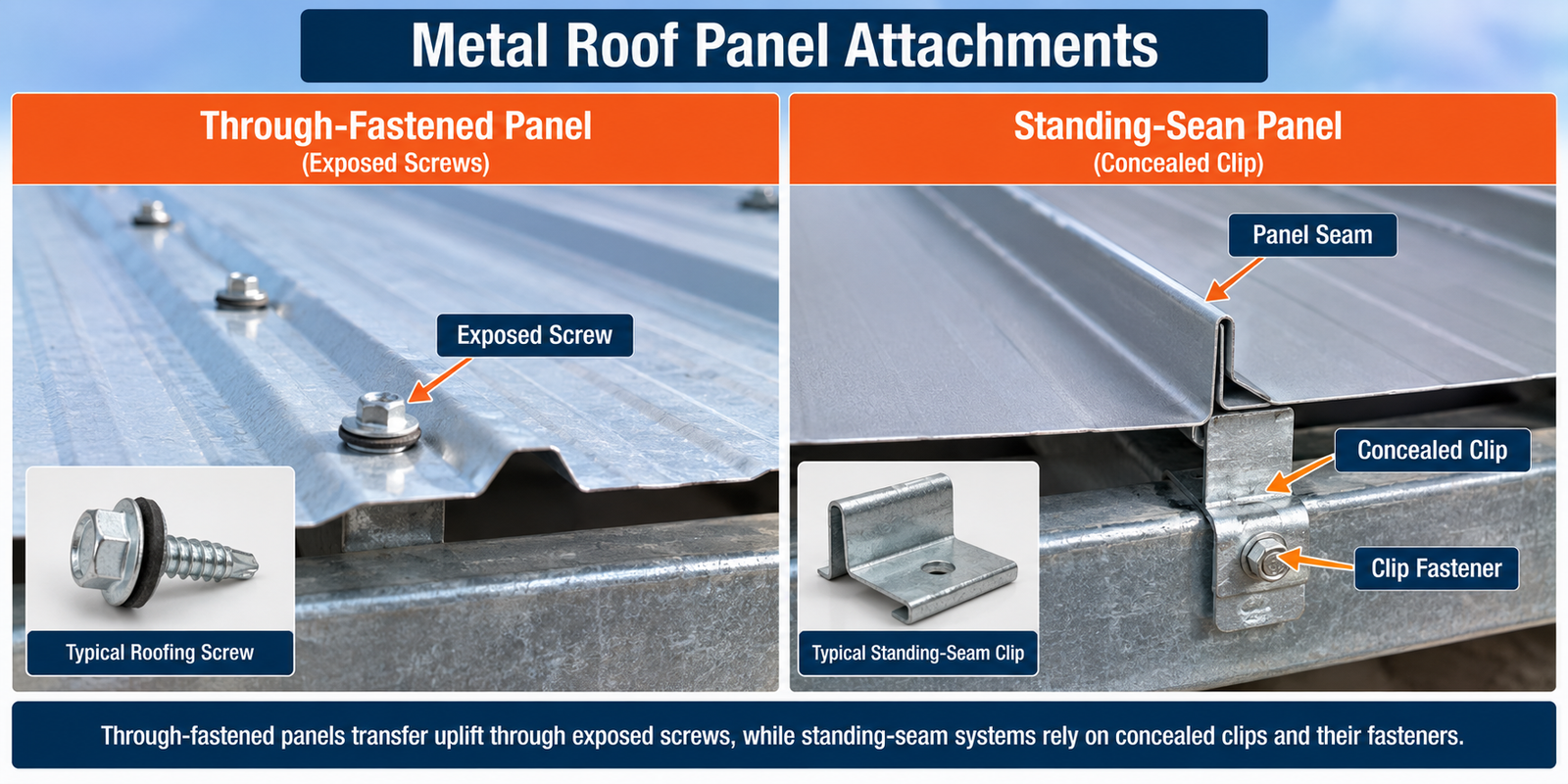
Exposed-fastener panels, standing-seam panels, and insulated panels each have distinct attachment methods and support requirements. Understanding which category a panel belongs to is the first step before looking at any span number.
Why There Is No Universal Span
Manufacturer load tables prove that panel capacity is product-specific, not a fixed number by gauge.
Allowable load changes materially with span length, gauge or base steel thickness, panel profile and depth, yield strength, single, 2, 3, or 4-span continuity, positive or gravity load, negative wind or uplift load, deflection criteria, and fastener or clip capacity. MBCI’s current PBU roof-panel table publishes spans from 3 to 9 ft for 29, 26, 24, and 22-gauge panels, with separate negative wind and live-load/deflection capacities for 1, 2, 3, and 4-span conditions. That does not mean every metal panel can span 9 ft; it proves why the exact panel table matters. MBCI’s corrugated-panel table gives values from 2 to 5 ft, again with dramatically different capacities depending on gauge and continuity.
What Is Metal Roof Panel Span?
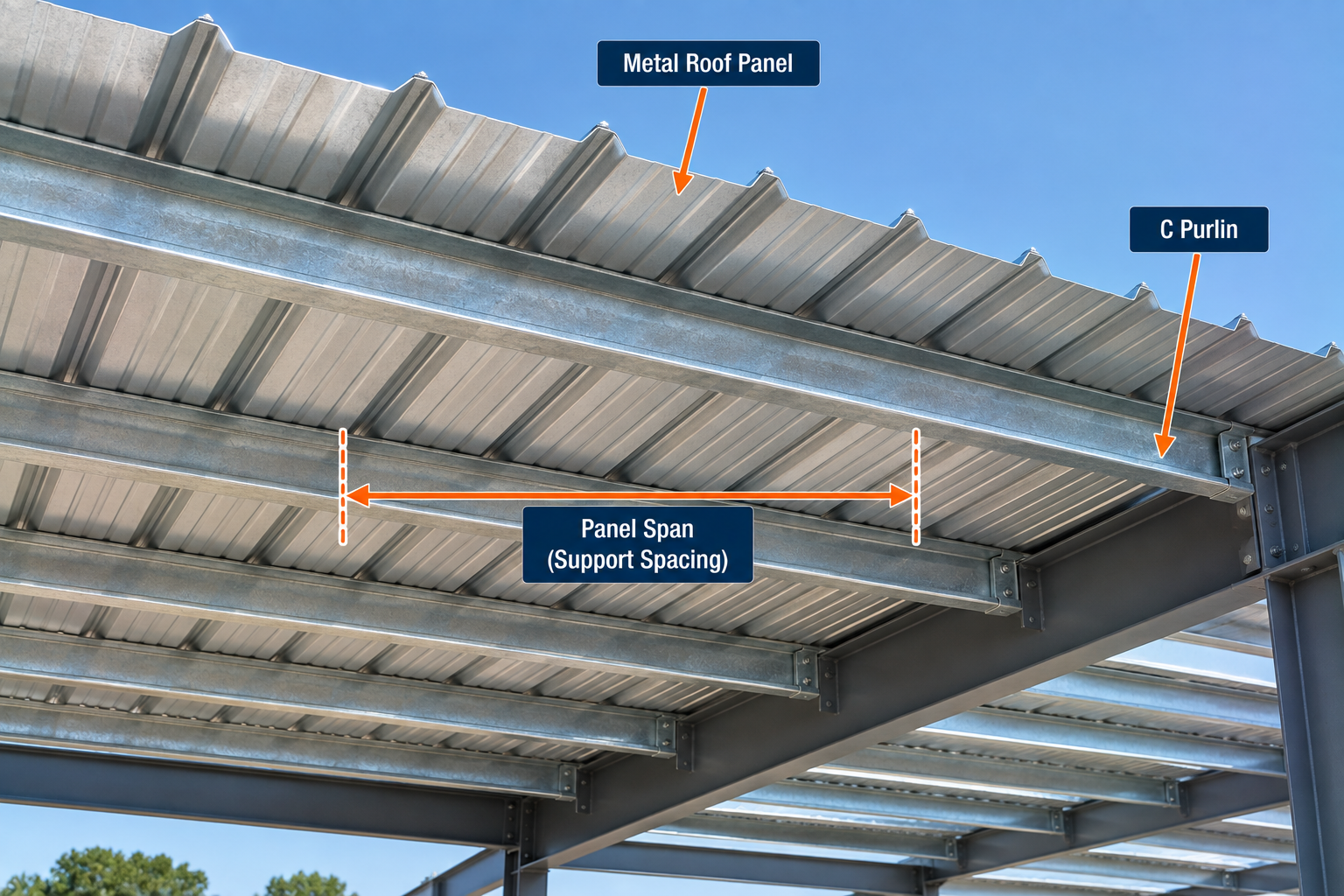
The distance between adjacent structural supports carrying the metal roof panel.
Supports may include purlins, joists, rafters, sub-purlins, or solid structural decking. For an open-framed metal building, panel span is approximately equal to purlin spacing.
Metal Roof Panel Span vs Purlin Spacing
Essential distinction between panel capacity and framing layout.
| Term | Definition |
|---|---|
| Panel Span | Distance the roof sheet or panel bridges between supports |
| Purlin Spacing | Distance between those supports |
For ordinary repetitive framing, panel span approximately equals purlin spacing. This makes the Purlin Spacing Chart the strongest sibling reference to this page: that page covers the framing-side decision, while this page covers the panel-side capacity limit.
What Determines Allowable Metal Roof Panel Span?
Gauge alone cannot determine allowable panel span.
| Factor | Why It Matters |
|---|---|
| Panel Profile / Rib Depth | Determines section stiffness and bending strength |
| Panel Width | Affects section properties per panel |
| Base Steel Thickness | Directly affects strength and stiffness |
| Steel Yield Strength | Sets allowable stress used in design |
| Single vs Multiple Spans | Continuity changes internal moment distribution |
| Positive / Inward Load | Governs gravity-direction capacity |
| Negative Wind / Uplift Load | Often the governing check, different load path |
| Fastener or Clip System | Can govern before panel bending does |
| Purlin/Support Width | Affects fastener bearing and pullout resistance |
| Roof Slope | Affects installation and system eligibility |
| Deflection Criterion | Serviceability limit separate from strength |
| Panel End Conditions | Affects behavior near eaves, ridges, and endlaps |
| Tested System Approval | Approval applies to the tested assembly, not the panel name alone |
Structural vs Architectural Metal Roof Panels
A critical distinction that affects whether open-framing span data even applies.
| Panel Category | Support Requirement |
|---|---|
| Structural Metal Roof Panel | Can span directly between spaced structural supports |
| Architectural Metal Roof Panel | Typically requires solid deck or closely fitted substrate |
The IBC recognizes structural panel roof systems where the panel functions as both roof covering and structural support for loads. Do not give open-framing span values to a panel intended for solid decking.
Open Framing vs Solid Deck Applications
Building codes distinguish these installation types explicitly.
| Installation | Does Panel Structurally Span? | Main Support |
|---|---|---|
| Open framing | Yes | Purlins/joists |
| Solid deck | Minimal structural open span | Deck/sheathing |
| Closely fitted deck | Supported continuously | Deck |
| Structural insulated panel | System-specific | Framing |
The 2024 IRC requires metal roof panels to be installed over solid or closely fitted structural sheathing unless the panel is specifically designed for spaced supports. IBC provisions likewise distinguish panels over solid decks from structural metal-panel systems designed for open framing.
Through-Fastened Roof Panel Span Chart
MBCI’s PBU panel is used here as a real, verified example, not a universal figure.
| Panel | Coverage | Rib Height | Gauge Options | Min. Slope |
|---|---|---|---|---|
| MBCI PBU | 36 in. | 3/4 in. | 26 ga standard; 24 and 22 ga optional | 1:12 |
MBCI’s PBU allowable-load chart covers spans from 3 to 9 ft depending on product, gauge, and load condition. Do not generalize these spans to all exposed-fastener panels; each manufacturer’s profile has its own tested load table.
Corrugated Metal Panel Span Chart
Shallow corrugated profiles behave very differently from deeper structural panels.
| Gauge | Published Span Range | Span Conditions Covered |
|---|---|---|
| 29 ga | 2 to 5 ft | 1 through 4 spans |
| 26 ga | 2 to 5 ft | 1 through 4 spans |
MBCI’s published corrugated-panel table demonstrates spans from 2, 2.5, 3, 3.5, 4, 4.5, to 5 ft, with different load values for 29 and 26-gauge sheets across 1 through 4 spans. A shallow corrugated panel can have a very different span and load envelope from a deeper structural rib panel of the same gauge.
R-Panel / PBR / PBU Panel Span
Common structural exposed-fastener roof panels grouped by shared characteristics.
These panels typically have deeper ribs, side laps, direct fasteners, open-framing capability, and higher structural span capability than shallow decorative profiles in many systems. Exact performance still depends on the manufacturer. MBCI’s verified PBU data (36-in. coverage, 3/4-in. rib, 26-gauge standard with 24 and 22-gauge options, spans from 3 to 9 ft) is a real example from this product family, not a rule for every R-panel-style product.
Standing-Seam Metal Roof Panel Span
Standing-seam panels need separate treatment because they attach through clips rather than direct fasteners.
| Product | Coverage | Rib Height | Gauge Options | Min. Slope | Substrate |
|---|---|---|---|---|---|
| MBCI SuperLok | 12 or 16 in. | 2 in. | 24 ga standard; 26 and 22 ga options | 1/2:12 | Open framing (purlins/bar joists) or deck |
| MBCI LokSeam | 12, 16, or 18 in. | 1 3/4 in. | 24 ga standard, other options available | 3:12 | Open framing or solid substrate |
Standing-seam panel allowable span must be taken from the exact panel/clip/load table, since the two verified products above differ in coverage, rib height, and minimum slope requirements despite both being standing-seam systems.
Panel Clip Spacing and Support Conditions
In standing-seam construction, clip spacing along the slope generally corresponds to panel support spacing.
Fixed clips attach the panel rigidly at that point, while floating or sliding clips accommodate thermal movement and can reduce lateral restraint compared with a fixed connection. Clip height, insulation conditions, and fastener substrate all affect real clip performance. National roof-framing design guidance specifically separates standing-seam purlin-system behavior from through-fastened systems because panel and clip restraint behave differently.
Panel Gauge vs Actual Base-Metal Thickness
A strong editorial rule for this entire page.
| Gauge | Minimum Decimal Base Thickness (in.) |
|---|---|
| 26 ga | 0.0180 |
| 24 ga | 0.0230 |
| 22 ga | 0.0296 |
Metal Sales explicitly recommends specifying minimum decimal thickness rather than gauge alone for its standing-seam specification. These specific decimal values apply to that Metal Sales specification and should not be presented as universal for every manufacturer’s product without confirming that manufacturer’s own published thickness.
Editorial Rule
Use decimal base-metal thickness alongside gauge in specifications and comparisons, rather than relying on gauge labels alone.
How Panel Thickness Affects Span
Thicker sheet generally helps, but it is not the only variable.
All else equal, thicker sheet generally increases section stiffness, bending strength, and allowable load. However, a 24-gauge panel is not automatically allowed to span farther than every 26-gauge panel, because panel profile, steel grade, clip or fastener system, and continuity also matter. Use manufacturer tables rather than gauge-only span rules.
Panel Rib Height, Profile, and Coverage Width
Deeper profiles often provide greater structural efficiency, but rib height alone does not rank panels.
Important geometry includes rib height, rib spacing, pan width, minor ribs, and corrugation shape. A shallow corrugated profile, a 3/4-in. rib exposed-fastener panel, and a 1 3/4 to 2-in. standing-seam profile each behave differently, but panels should not be ranked solely from rib height without checking the manufacturer’s tested load table.
Panel Coverage Width and Structural Span
Coverage width is perpendicular to span, but it still affects cross-sectional section properties per panel, sidelap count, and clip or fastener layout. Verified standing-seam products range from 12 in. to 18 in. coverage depending on the specific product. Panel coverage width should never be confused with panel support span, since they describe different directions of the panel entirely.
Single-Span vs Multi-Span Metal Panels
One of the most important distinctions in reading a panel load table.
| Condition | Description |
|---|---|
| Single Span | Panel supported at two lines only |
| Multi-Span (2, 3, 4-span) | Panel continuous over intermediate supports |
MBCI’s PBU and corrugated tables show substantially different allowable loads for the same gauge and span depending on continuity. Do not use a 3-span capacity for a single-span condition.
Equal vs Unequal Panel Spans
Manufacturer tables commonly assume uniform span lengths.
MBCI explicitly notes this assumption in its corrugated-panel allowable-load table. Conditions such as a short end bay, irregular purlin spacing, a roof opening, or a partial span cannot automatically use equal-span table values without engineering review.
Positive / Gravity Load Capacity
Inward or downward loading on the panel.
Potential gravity loads include panel self-weight, snow, roof live load, maintenance loads, and rain or ponding where applicable. MBCI identifies live-load and deflection values separately from negative wind values in its roof-panel tables, which reflects how these are two distinct engineering checks.
Negative Wind / Uplift Capacity
A separate check from gravity, often the governing condition.
Wind suction pulls the panel away from its supports. Allowable uplift can depend on panel bending, seam strength, fastener pullout, fastener pullover, clip strength, and support thickness. MBCI explicitly states in its PBU table that panel pullover and screw pullout must be checked separately from the published panel load chart, which is a critical page message: panel bending capacity alone does not establish allowable roof span under uplift.
Fastener Pullout, Pullover, and Clip Capacity
Two distinct failure modes that can govern before panel bending does.
| Failure Mode | Description |
|---|---|
| Pullout | Fastener pulls out of the supporting purlin or deck |
| Pullover | Panel sheet pulls over the fastener head or washer |
Panel bending capacity alone does not establish allowable roof span under uplift; support thickness matters directly to pullout resistance. For purlin thickness data relevant to this check, see the C Purlin Size Chart and Z Purlin Size Chart.
Standing-Seam Clip Capacity
For standing seam, the uplift load path runs from panel seam to clip, to clip fastener, to purlin or deck. All pieces can govern. Relevant factors include clip type, fixed versus floating behavior, number and type of fasteners, support thickness, and tested system approvals. Do not combine exposed-fastener pullout values with standing-seam clip values, since they describe different connection systems entirely.
Metal Roof Panel Deflection Limits
Span tables are often limited by deflection as well as strength.
Examples from manufacturer tables show project-specific criteria such as L/180 for certain exposed roof-panel live-load checks and L/240 for a particular insulated standing-seam roof system. There is no single universal deflection ratio for every metal roof panel system; use the exact manufacturer, code, or project requirement that applies.
Snow and Drift Effects on Panel Span
Span must be checked against the full range of applicable snow conditions.
ASCE 7-22 is the current U.S. national loading framework and includes dedicated snow-load provisions covering balanced snow, unbalanced snow, drift, sliding snow, and applicable combinations. A panel that works at 5-ft spacing in a low-snow region may not work at the same spacing in a high-snow region.
Snow Drift and Local Panel Span Demand
Drifts can occur near higher roof transitions, parapets, obstructions, and valleys, producing localized pressures much higher than field loading. The same panel spacing throughout the roof does not guarantee the same reserve capacity everywhere.
Wind Zones and Edge/Corner Uplift
Roof uplift is often not uniform across the roof surface.
Different pressures can apply to field, edge, and corner zones under the applicable ASCE 7 method. One project may need closer supports, a thicker panel, more fasteners or clips, stronger clips, or thicker purlin support depending on zone, without one universal solution being required for every case.
ASTM E1592, UL 580, and FM 4474 Testing
A major standards and testing section explaining why tested system configuration matters.
| System | Applicable Testing |
|---|---|
| Standing Seam | ASTM E1592, FM 4474 |
| Through-Fastened | ASTM E1592, FM 4474, UL 580 |
IBC requirements for structural metal panel roof systems recognize this kind of testing for applicable wind-resistance evaluation. This explains why a tested system configuration, not just a panel name, is what carries a wind-resistance rating.
Manufacturer and High-Wind Product Approvals
An approval applies to the tested assembly, not just the panel name.
Relevant approval programs include Florida Product Approval, Miami-Dade NOA, UL assemblies, and FM approvals. Manufacturers list product-specific approvals with defined panel gauge, substrate, and maximum design pressure conditions. A panel approved under one gauge, substrate, and fastening pattern cannot be assumed to carry the same approval under a different configuration.
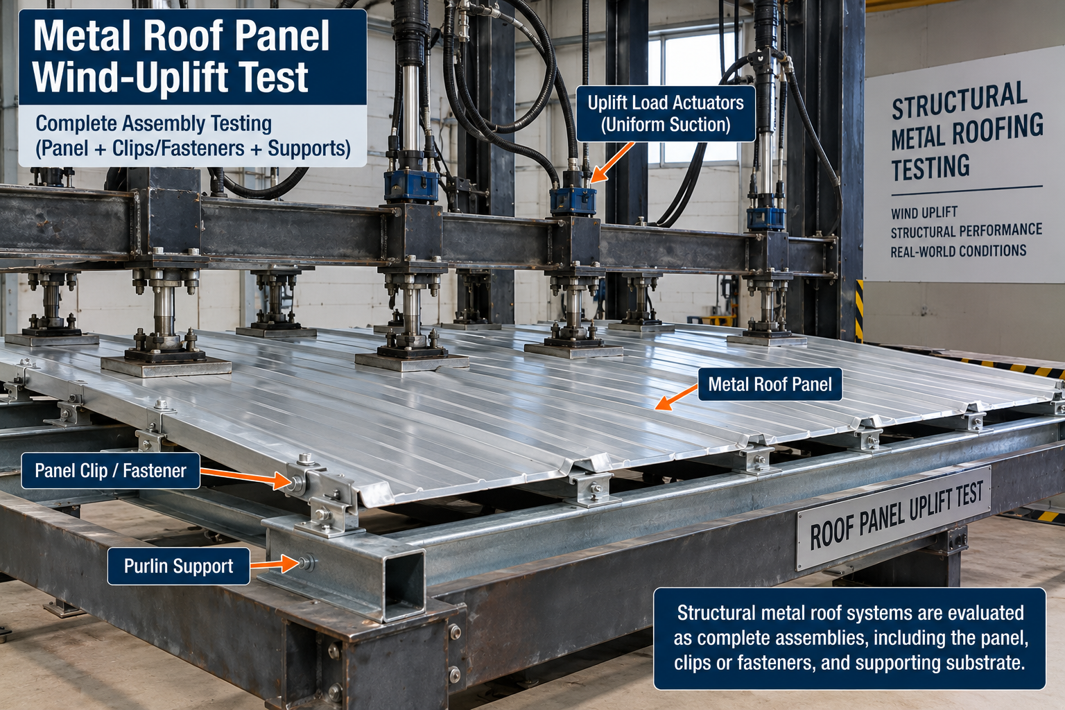
Support/Purlin Thickness and Panel Capacity
A support is not just a line in a diagram; its thickness matters directly.
Purlin or substrate thickness affects screw pullout, clip fastener capacity, and overall connection strength. A panel tested over one support thickness cannot automatically be assumed equivalent over a thinner purlin, which is why this page links directly to purlin thickness data on the C Purlin Size Chart and Z Purlin Size Chart.
Roof Slope and Panel Span
Slope requirements are panel-specific, not universal.
Roof slope affects drainage, panel system eligibility, hydrostatic and hydrokinetic behavior, snow behavior, clip movement, and installation requirements. Verified current products demonstrate substantial variation: MBCI SuperLok has a minimum slope of 1/2:12, while MBCI LokSeam requires a minimum slope of 3:12. This proves slope requirements are panel-specific; do not use one universal metal-roof slope requirement. For general pitch geometry, see the Roof Pitch Chart.
Structural vs Architectural Standing Seam
A major search-intent differentiator and a potentially serious specification error if confused.
| Type | Typical Support |
|---|---|
| Structural Standing Seam | Designed to span across purlins or open framing |
| Architectural Standing Seam | Often intended over solid deck, sheathing, or continuous substrate |
A standing-seam appearance alone does not tell you whether the panel is structurally capable of open framing. Verify the specific product’s structural rating and tested support conditions before assuming it can be installed over spaced purlins.
Insulated Metal Roof Panel Spans
A separate specialist category with completely product-specific span behavior.
Insulated panels combine an exterior skin, an insulation or core layer, and an interior liner. Historical manufacturer data show an insulated standing-seam panel evaluated over spans from 4 to 7 ft with separate gravity, uplift, and deflection criteria. Do not mix insulated metal panel span tables with single-skin roof panel tables, since the two systems behave structurally differently.
Roof Openings, End Laps, and Discontinuities
The ordinary field load table may not directly apply near these conditions.
Skylights, curbs, roof penetrations, panel endlaps, and ridge or eave conditions can create partial spans and local discontinuities. Additional support may be required at these locations rather than assuming the standard field span table applies without modification.
How to Read a Metal Roof Panel Load Table
One of the page’s strongest practical sections.
Panel Load Table Workflow
How to Determine Maximum Panel Span
A calculation and decision workflow that directly complements the Purlin Spacing Chart.
Maximum Span Determination Workflow
Common Mistakes and Chart Limitations
Assuming all 26-gauge panels span the same distance
Profile differences make gauge alone insufficient to predict span.
Assuming 24 gauge always spans farther than 26 gauge
Profile, grade, and continuity also matter, regardless of the profile compared.
Using gauge without decimal base thickness
Always confirm the manufacturer’s actual published thickness.
Confusing panel coverage width with panel span
Coverage is perpendicular to span and describes a different dimension.
Confusing purlin span with panel span
These describe framing-side and panel-side distances respectively.
Treating corrugated panel like a deep-rib structural panel
Shallow corrugated profiles have a narrower span envelope.
Treating architectural standing seam as structural standing seam
Architectural panels often require solid deck support instead of open framing.
Using multi-span capacity for a single-span condition
Continuity changes allowable load at the same span.
Ignoring unequal support spacing
Manufacturer tables commonly assume uniform span lengths.
Checking gravity only
Wind uplift is frequently the governing check.
Ignoring fastener pullout/pullover
Connections can govern before panel bending capacity does.
Ignoring clip capacity
Standing-seam uplift depends on the full clip and fastener load path.
Ignoring support thickness
Fastener capacity depends partly on the purlin or substrate thickness.
Ignoring roof wind zones
Edge and corner zones typically see higher uplift demand than field areas.
Ignoring snow drift
Localized drift loads can exceed field-area assumptions.
Ignoring deflection
Serviceability can control before strength does.
Assuming one manufacturer’s table applies to another panel
Each product’s load table applies only to that exact product.
Treating “5-ft maximum span” as a universal industry rule
Actual allowable span is always product and load-condition specific.
Read before finalizing panel span or support spacing
No universal panel span applies to all metal roofing, and panel profile materially affects capacity. Gauge should be paired with actual base-metal thickness, and yield strength matters. Single and multi-span conditions differ, positive and negative loads differ, and wind uplift may govern before gravity does. Fastener or clip capacity can govern before panel bending, and support thickness affects attachment capacity. Deflection may govern before strength, and panel approval may restrict substrate or support conditions, with architectural panels often requiring solid decking. Snow and wind loads vary by location and roof geometry, and manufacturer load tables apply only to their tested or calculated product and stated assumptions. Final support spacing must follow approved construction documents and manufacturer engineering.
Metal Roof Panel Span FAQs
Download the Metal Roof Panel Span Chart
Get a printable reference including the panel type comparison, load-path diagrams, and standards summary on this page for jobsite or office use.
![Rebar Size Chart - Complete #3 to No. 20 [64] Diameter, Area & Grade Reference](https://concretecalculate.com/wp-content/uploads/2026/07/Rebar-Size-Chart-2026-Complete-3-to-No.-20-64-Diameter-Area-Grade-Reference-390x220.png)