Rebar Lap Splice Chart 2026: Complete Tension & Compression Reference
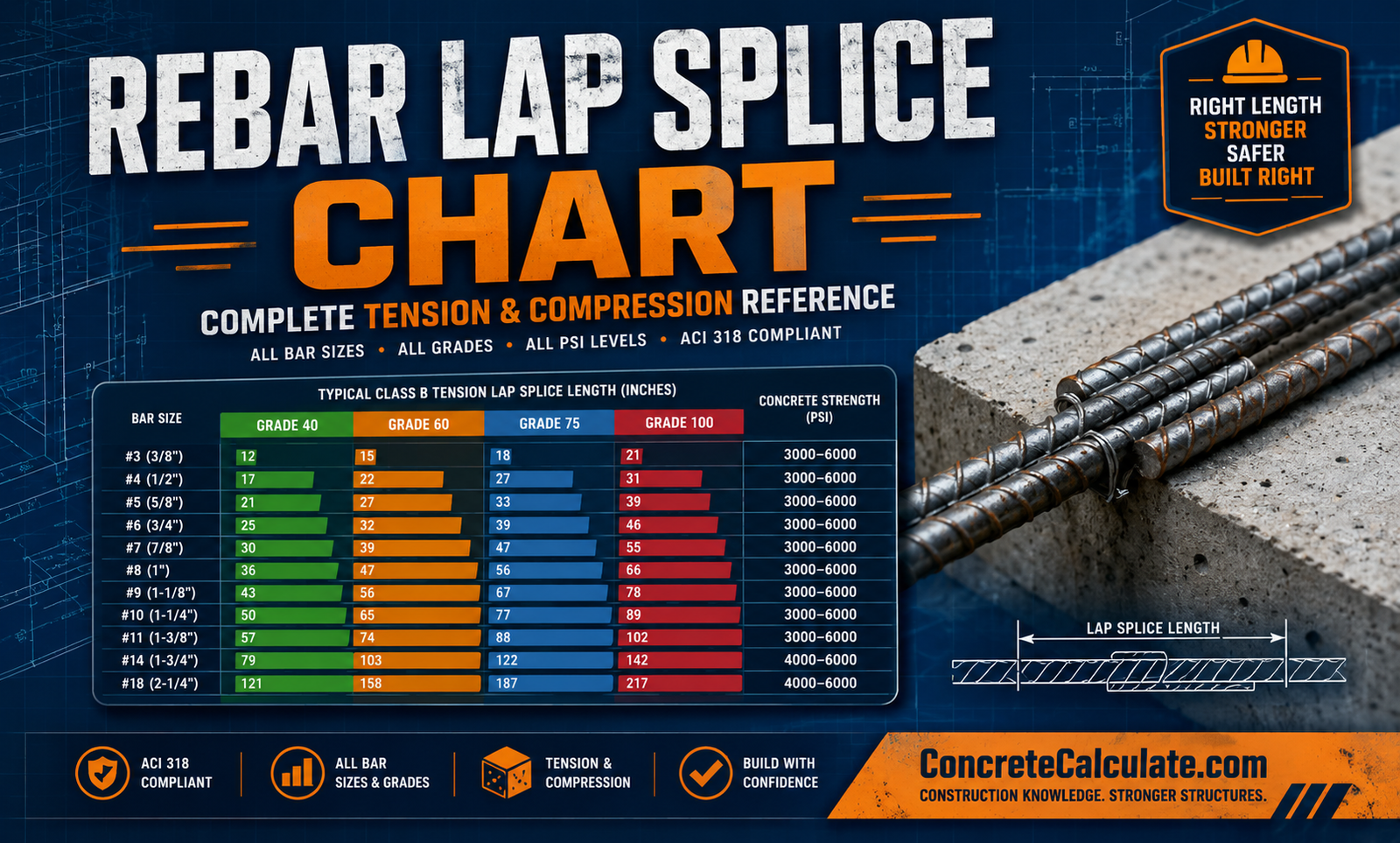
Rebar Lap Splice Chart
Complete Tension & Compression Reference
The complete lap splice reference for contractors, engineers, and inspectors — tension/compression lengths by bar size, grade, PSI, and coating.
 Reviewed by Muhammad Ramzan Babar, PhD Researcher (Plasma Physics) & Calculator Developer — View Profile
⭐ Master Rebar Lap Splice Chart
Class B tension lap splice lengths for bar sizes #3–#18, Grade 60, at 4,000 PSI concrete — the most common design combination.
How to Read This Chart
Class B lap splice = 1.3 × development length (ld), with a 12-inch minimum, per ACI 318 §25.5.2. Need exact bar quantities for your project? Use our Rebar Calculator.
| Bar Size | Diameter (in) | Class B Tension Lap (in) | Compression Lap (in) |
|---|---|---|---|
| #3 | 0.375 | 19 | 15 |
| #4 | 0.500 | 25 | 19 |
| #5 | 0.625 | 31 | 24 |
| #6 | 0.750 | 37 | 29 |
| #7 | 0.875 | 54 | 34 |
| #8 | 1.000 | 62 | 39 |
| #9 | 1.128 | 70 | 44 |
| #10 | 1.270 | 79 | 49 |
| #11 | 1.410 | 87 | 54 |
| #14 | 1.693 | N/A (mechanical/welded only) | 65 |
| #18 | 2.257 | N/A (mechanical/welded only) | 87 |
Values shown for Grade 60, uncoated, normal-weight concrete at 4,000 PSI, “other than top” bar position. Per ACI 318-19 §25.5.2, #14/#18 bars cannot be lap spliced in tension. Source: ACI 318, CRSI.
Tension Lap Splice Chart
Class B tension lap splice lengths for #3–#11 bars, comparing Grade 40 and Grade 60 at 4,000 PSI concrete.
| Bar Size | Grade 40 (in) | Grade 60 (in) |
|---|---|---|
| #3 | 13 | 19 |
| #4 | 17 | 25 |
| #5 | 21 | 31 |
| #6 | 25 | 37 |
| #7 | 36 | 54 |
| #8 | 41 | 62 |
| #9 | 47 | 70 |
| #10 | 53 | 79 |
| #11 | 58 | 87 |
Class A splice (1.0 × ld) may be used only when As,provided/As,required ≥ 2.0 and ≤50% of bars are spliced at one location.
Compression Lap Splice Chart
Compression splices are shorter than tension splices because concrete bearing helps transfer load directly.
| Bar Size | Grade 60 Compression Lap (in) | vs Tension Lap (in) |
|---|---|---|
| #3 | 15 | 19 |
| #4 | 19 | 25 |
| #5 | 24 | 31 |
| #6 | 29 | 37 |
| #8 | 39 | 62 |
| #10 | 49 | 79 |
| #11 | 54 | 87 |
Compression laps are roughly 20-25% shorter than tension laps for the same bar and grade. ACI 318 restricts compression lap splices to bars #11 and smaller.
Rebar Lap Splice Length by Bar Size
Quick-reference typical Class B tension lap length at 4,000 PSI, Grade 60.
| Bar Size | Diameter (in) | Typical Lap Length (in) |
|---|---|---|
| #3 | 0.375 | 19 |
| #4 | 0.500 | 25 |
| #5 | 0.625 | 31 |
| #6 | 0.750 | 37 |
| #7 | 0.875 | 54 |
| #8 | 1.000 | 62 |
| #9 | 1.128 | 70 |
| #10 | 1.270 | 79 |
| #11 | 1.410 | 87 |
Rebar Lap Splice Length by Grade
Higher grade steel requires longer splices since yield strength — and the force to be transferred — is greater.
| Grade | Yield Strength (psi) | #5 Bar Tension Lap (in) | #8 Bar Tension Lap (in) |
|---|---|---|---|
| Grade 40 | 40,000 | 21 | 41 |
| Grade 60 | 60,000 | 31 | 62 |
| Grade 75 | 75,000 | 39 | 77 |
| Grade 80 | 80,000 | 41 | 82 |
| Grade 100 | 100,000 | 52 | 103 |
Estimated proportionally to yield strength (fy) at 4,000 PSI concrete. Always verify with project-specific structural calculations for Grade 75+.
Lap Splice Length in Inches & Millimeters
Class B tension lap splice, Grade 60, 4,000 PSI — dual-unit reference.
| Bar Size | Lap Length (in) | Lap Length (mm) |
|---|---|---|
| #3 | 19 | 483 |
| #4 | 25 | 635 |
| #5 | 31 | 787 |
| #6 | 37 | 940 |
| #7 | 54 | 1,372 |
| #8 | 62 | 1,575 |
| #9 | 70 | 1,778 |
| #10 | 79 | 2,007 |
| #11 | 87 | 2,210 |
Development Length vs Lap Splice Chart
These two lengths serve different purposes — knowing the difference prevents costly under-reinforcement.
| Type | Formula (per ACI 318) | Purpose | Typical Applications |
|---|---|---|---|
| Development Length (ld) | Per §25.4.2.4 (bar size, cover, spacing dependent) | Anchor a single bar to develop full strength | Bar termination, embedment into supports |
| Class A Lap Splice | 1.0 × ld | Splice two bars with excess reinforcement | Low-stress zones, staggered splices |
| Class B Lap Splice | 1.3 × ld (min. 12 in) | Splice two bars, general/default case | Most slabs, walls, footings, beams |
| Compression Lap Splice | ~0.0005×fy×db (Grade ≤ 60) | Splice bars carrying compressive force | Columns, compression members |
⭐ Rebar Lap Splice by Construction Application
Typical splice recommendations by structural element — always verify against project drawings.
| Application | Typical Lap Splice Recommendation |
|---|---|
| Footings | Class B tension, staggered, #4–#5 bars (25–31 in) |
| Foundations | Class B tension, #4–#5 bars (25–31 in) |
| Slabs | Class B tension, #3–#4 bars (19–25 in) |
| Beams | Class B tension, #5–#8 bars (31–62 in), staggered |
| Columns | Compression lap, #6–#11 bars (29–54 in) |
| Walls | Class B tension or non-contact splice, #4–#6 bars |
| Retaining Walls | Class B tension, #4–#6 bars (25–37 in) |
| Bridge Decks | Class B tension, #5–#8 bars, often epoxy-coated (increase 20-50%) |
Contact Lap Splice vs Non-Contact Lap Splice
The choice affects constructability and load transfer path.
| Type | Minimum Spacing | Typical Uses | Advantages | Design Considerations |
|---|---|---|---|---|
| Contact Lap Splice | Bars touching/wired together | Slabs, footings, beams, most general work | Simple, predictable, standard code coverage | None beyond standard lap length |
| Non-Contact Lap Splice | Up to lesser of 1/5 lap length or 6 in apart | Walls, congested reinforcement zones | Easier placement in tight forms | Wider spacing may require transverse reinforcement check |
Rebar Lap Splice by Concrete Strength
Higher concrete compressive strength improves bond, shortening required splice length. Cross-reference with our Concrete PSI Chart.
| Bar Size | 3,000 PSI | 3,500 PSI | 4,000 PSI | 5,000 PSI | 6,000 PSI |
|---|---|---|---|---|---|
| #3 | 22″ | 20″ | 19″ | 17″ | 15″ |
| #4 | 29″ | 27″ | 25″ | 23″ | 21″ |
| #5 | 36″ | 33″ | 31″ | 28″ | 26″ |
| #6 | 43″ | 40″ | 37″ | 34″ | 31″ |
| #7 | 63″ | 58″ | 54″ | 49″ | 45″ |
| #8 | 72″ | 67″ | 62″ | 56″ | 51″ |
Grade 60, Class B tension splice, uncoated bars, “other than top” position. Values decrease as f’c increases per the (cb+Ktr)/db bond term in ACI 318.
Rebar Lap Splice by Epoxy Coating
Epoxy coating reduces bond strength between bar and concrete, requiring longer splice lengths.
| Bar Size | Uncoated (in) | Epoxy-Coated, ψe=1.2 (in) | Epoxy-Coated, ψe=1.5 (in) |
|---|---|---|---|
| #3 | 19 | 23 | 29 |
| #4 | 25 | 30 | 38 |
| #5 | 31 | 37 | 47 |
| #6 | 37 | 44 | 56 |
| #8 | 62 | 74 | 93 |
Coating Factor Rule (ψe)
Per ACI 318, use ψe = 1.5 when cover to bar center is less than 3 bar diameters or clear spacing is less than 6 bar diameters; otherwise use ψe = 1.2. The product of coating and top-bar factors is capped at 1.7.
Hooked Bars vs Straight Bars Chart
Hooks reduce required embedment length when space is limited.
| Type | Relative Length Needed | Typical Applications |
|---|---|---|
| Standard 90° Hook | ~40-50% shorter than straight development | Beam-column joints, limited embedment depth |
| Standard 180° Hook | ~40-50% shorter than straight development | Footing dowels, wall-to-footing connections |
| Straight Development | Full ld (baseline) | Slabs, walls, straight-run reinforcement with adequate space |
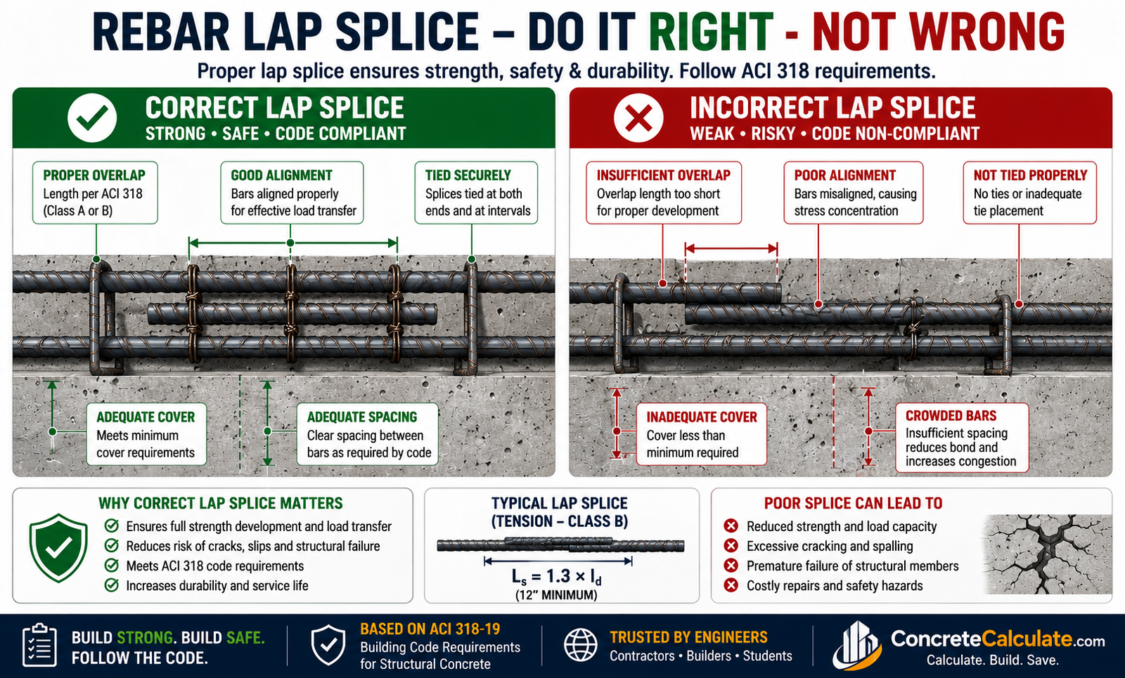
⭐ Visual Rebar Lap Splice Guide
Correct vs incorrect splicing at a glance — critical for field training.
Correct Lap Splice
Full required overlap length, bars aligned and tied, proper clear spacing maintained, staggered from adjacent splices.
Incorrect Lap Splice
Overlap too short, bars misaligned or offset, insufficient clear spacing, all splices at the same critical section.
Common Residential Lap Splice Sizes
Typical splice lengths for home construction, Grade 60, 3,500-4,000 PSI.
| Application | Bar Size | Typical Lap Splice |
|---|---|---|
| Driveways | #3–#4 | 19–25 in |
| Sidewalks | #3 | 19–20 in |
| Patios | #3 | 19–20 in |
| Garage Floors | #3–#4 | 19–25 in |
| House Foundations | #4–#5 | 25–31 in |
Common Commercial Lap Splice Sizes
Typical splice lengths for commercial and industrial structures, often requiring larger bars and higher grades.
| Application | Bar Size | Typical Lap Splice |
|---|---|---|
| Warehouses | #4–#6 | 25–37 in |
| Multi-Story Buildings | #8–#11 | 62–87 in (or coupler) |
| Parking Structures | #5–#7 | 31–54 in |
| Bridges | #5–#8 | 31–62 in, often epoxy-coated (+20-50%) |
| Industrial Floors | #4–#6 | 25–37 in |
Rebar Lap Splice Selection Guide
Decision table for choosing bar size and splice length by project type.
| Project | Bar Size | Recommended Lap Splice |
|---|---|---|
| Backyard patio | #3 | 19 in (Class B) |
| Standard driveway | #4 | 25 in (Class B) |
| House footing | #4–#5 | 25–31 in (Class B, staggered) |
| Retaining wall | #4–#5 | 25–31 in vertical, non-contact if congested |
| Suspended beam | #7–#8 | 54–62 in (Class B, staggered) |
| High-rise column | #10–#11 | 49–54 in (compression) or mechanical coupler |
Contractor Worked Examples
Real-world lap splice sizing scenarios.
#4 Bars in a Residential Footing
#5 Bars in a Retaining Wall
#6 Bars in a Slab
#8 Bars in a Beam
Column Reinforcement Splice
Common Lap Splice Mistakes
Field errors that compromise structural performance.
Insufficient overlap
Cutting the lap length short — even by a few inches — can prevent full force transfer between bars and cause bond failure.
Splicing at maximum stress locations
Placing splices at points of peak moment or shear (like beam mid-span) increases failure risk; splices belong in lower-stress zones.
Poor concrete cover
Inadequate cover reduces bond strength and increases corrosion risk, effectively shortening the splice’s real-world capacity.
Misaligned bars
Bars that aren’t parallel or properly overlapped reduce the effective splice length and create stress concentrations.
Incorrect bar spacing
Spacing bars too closely together at a splice location reduces bond strength and may require a longer development length per code.
Frequently Asked Questions
📥 Download Rebar Lap Splice Chart PDF
Use your browser’s print function to instantly save this page as a PDF. This avoids broken file links and gives you an always up-to-date printable field reference for engineers, contractors, inspectors, and students.