Countersink Size Chart – Diameter, Depth & Angle Reference
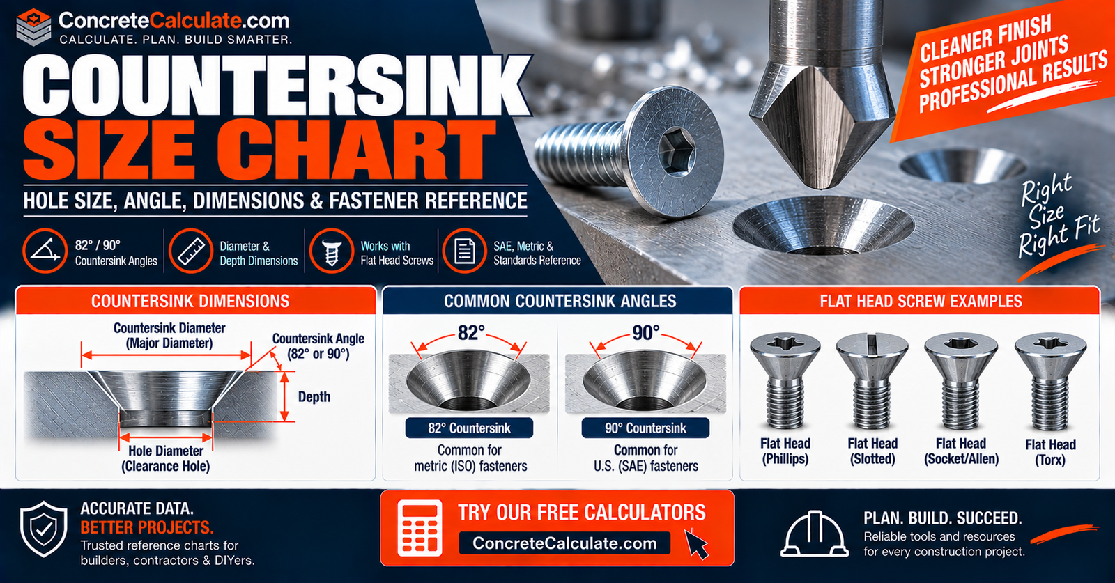
Countersink Size Chart
Diameter, Depth & Angle Reference
Countersink major diameter, included angle, depth, clearance-hole relationship, and correct head-angle matching for 82-degree, 90-degree, and 100-degree flat-head screws and rivets under ASME and ISO standards.
 Reviewed by Muhammad Ramzan Babar, PhD Researcher (Plasma Physics) & Calculator Developer, View Profile
Countersink angle must match the fastener head angle
There is no one universal countersink angle for all flat-head fasteners. Many U.S. machine screws use 82-degree heads, metric ISO countersunk screws use 90-degree geometry, and aerospace or special U.S. forms can use 100-degree heads. A countersink diameter cannot be chosen correctly until the fastener head angle and actual head diameter are known.
Countersink Size Chart, Quick Reference
Use separate angle groups. Do not mix 82-degree, 90-degree, and 100-degree fasteners into one generic row.
Inch Countersink Size Chart
| Screw Size | Head Form | Clearance/Pilot Hole | Head Angle | Countersink Major Diameter Basis | Depth Basis |
|---|---|---|---|---|---|
| #6 | ASME flat head | Match required hole system | 82° or 100° | Actual specified head diameter | Formula from D, d, θ |
| #8 | ASME flat head | Match required hole system | 82° or 100° | Actual specified head diameter | Formula from D, d, θ |
| #10 | ASME flat head | Match required hole system | 82° or 100° | Actual specified head diameter | Formula from D, d, θ |
| 1/4 in. | ASME flat head | Match required hole system | 82° or 100° | Actual specified head diameter | Formula from D, d, θ |
ASME B18.6.3 includes multiple 82-degree and 100-degree flat countersunk machine-screw head forms. Verify the individual fastener table before selecting the major countersink diameter.
Metric Countersink Size Chart
| Metric Screw | Clearance Hole | Head Angle | Countersink Diameter Basis | Depth Basis |
|---|---|---|---|---|
| M2 | Match ISO clearance class | 90° | ISO 7721/15065 head geometry | Formula from D, d, θ |
| M3 | Match ISO clearance class | 90° | ISO 7721/15065 head geometry | Formula from D, d, θ |
| M4 | Match ISO clearance class | 90° | ISO 7721/15065 head geometry | Formula from D, d, θ |
| M5 | Match ISO clearance class | 90° | ISO 7721/15065 head geometry | Formula from D, d, θ |
| M6 | Match ISO clearance class | 90° | ISO 7721/15065 head geometry | Formula from D, d, θ |
| M8 | Match ISO clearance class | 90° | ISO 7721/15065 head geometry | Formula from D, d, θ |
| M10 | Match ISO clearance class | 90° | ISO 7721/15065 head geometry | Formula from D, d, θ |
| M12 | Match ISO clearance class | 90° | ISO 7721/15065 head geometry | Formula from D, d, θ |
ISO 15065 specifies matched countersink dimensions for countersunk-head screws whose head configuration follows ISO 7721.
Countersink Angle Quick Reference
| Included Angle | Half-Angle | Typical Context |
|---|---|---|
| 60° | 30° | Specialty/tooling |
| 82° | 41° | Many U.S. flat-head machine screws |
| 90° | 45° | ISO metric countersunk screws |
| 100° | 50° | Aerospace/special U.S. flat-head |
| 120° | 60° | Specialty/tooling |
Angle before diameter
Identify the screw standard or head angle before recommending countersink diameter or depth. Screw nominal diameter alone is not sufficient.
What Is a Countersink?
A conical recess at the top of a hole that allows a countersunk head to sit flush with or below the surrounding surface.
Typical purposes include flush fastening, reduced snagging, smooth finished surfaces, aerodynamic surfaces, and improved assembly clearance.
Countersink vs Counterbore
Essential distinction.
| Feature | Countersink | Counterbore |
|---|---|---|
| Shape | Conical | Cylindrical |
| Bottom | Point/cone | Flat |
| Typical fastener | Flat head | Socket head |
| Key dimension | Angle + major diameter | Diameter + depth |
Countersink vs Chamfer
Not every chamfer is a functional countersink.
A chamfer may simply break a sharp edge. A countersink is dimensioned specifically by angle and major diameter to receive a flat-head fastener. This distinction matters in drawings and CNC programming.
Countersink Dimension Anatomy
The first major technical visual.
Countersink Diameter vs Screw Head Diameter
Major diameter normally relates closely to actual flat-head geometry.
The countersink major diameter normally relates closely to the flat-head screw’s maximum head diameter, depending on whether the head must sit flush, slightly recessed, or slightly proud, and on the drawing’s depth tolerance. You cannot choose the correct countersink diameter from nominal screw diameter alone; use the actual head geometry from the fastener standard or manufacturer data.
How to Calculate Countersink Depth
An excellent practical calculation section for machinists and CAD/CAM users.
Conical Countersink Formula
h = (D – d) / [2 tan(θ/2)], where D = countersink major diameter, d = hole diameter, and θ = included countersink angle.
90° Countersink
Since tan(45°) = 1, a 90° countersink simplifies to h = (D – d) / 2.
Illustrative 90° Geometry Example
Countersink Angle Chart
Tool angle must match required fastener head angle.
| Angle | Half-Angle | Typical Application |
|---|---|---|
| 60° | 30° | Specialty/tooling |
| 82° | 41° | U.S. flat-head machine screws |
| 90° | 45° | ISO metric flat-head screws |
| 100° | 50° | Aerospace/special U.S. flat-head |
| 120° | 60° | Specialty/tooling |
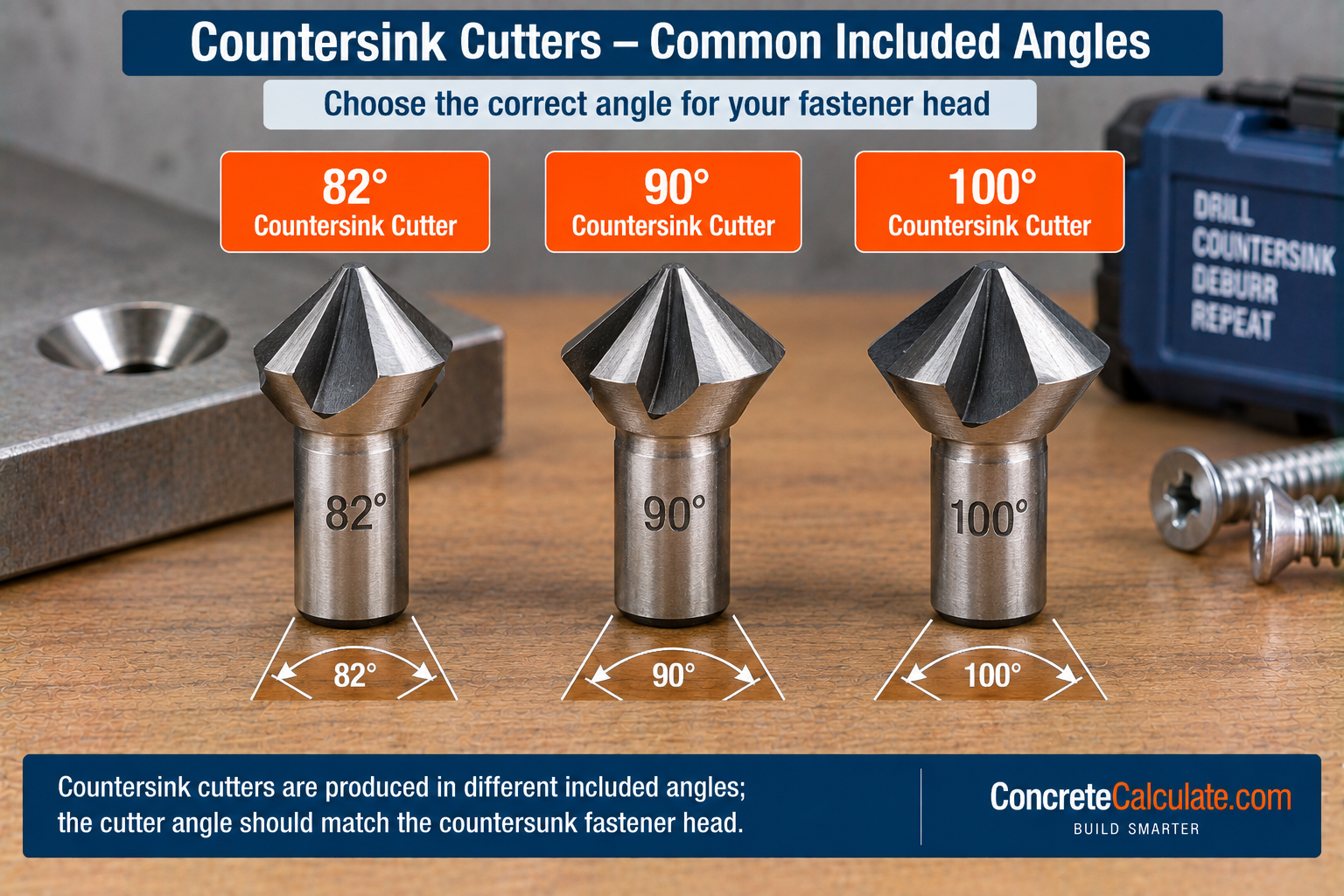
ISO 3294 standardizes countersink tools with included angles of 60°, 90°, and 120°. Other standards and commercial cutters cover 82° and 100° forms for the fasteners that require them.
82° Countersink Size Chart
Major U.S. section for standard 82° flat-head machine screw forms.
| Screw Size | Head Form | Clearance Hole | 82° Countersink Major Diameter | Flush Depth |
|---|---|---|---|---|
| #6 | ASME 82° flat head | Per required clearance class | Per actual specified head diameter | Calculated from D, d, 82° |
| #8 | ASME 82° flat head | Per required clearance class | Per actual specified head diameter | Calculated from D, d, 82° |
| #10 | ASME 82° flat head | Per required clearance class | Per actual specified head diameter | Calculated from D, d, 82° |
| 1/4 in. | ASME 82° flat head | Per required clearance class | Per actual specified head diameter | Calculated from D, d, 82° |
ASME B18.6.3 includes multiple 82° flat countersunk-head forms, including undercut forms. Do not replace head-specific ASME dimensions with a generic diameter-to-countersink ratio.
Use the Clearance Hole Size Chart to select the smaller pass-through hole below the countersink.
90° Metric Countersink Size Chart
Main metric section under the ISO 7721/ISO 15065 system.
| Metric Screw | Clearance Hole | Head Angle | 90° Countersink Diameter | Flush Depth |
|---|---|---|---|---|
| M3 | Per ISO 273 fit class | 90° | ISO 15065 matched head geometry | Calculated from D, d, 90° |
| M4 | Per ISO 273 fit class | 90° | ISO 15065 matched head geometry | Calculated from D, d, 90° |
| M5 | Per ISO 273 fit class | 90° | ISO 15065 matched head geometry | Calculated from D, d, 90° |
| M6 | Per ISO 273 fit class | 90° | ISO 15065 matched head geometry | Calculated from D, d, 90° |
| M8 | Per ISO 273 fit class | 90° | ISO 15065 matched head geometry | Calculated from D, d, 90° |
ISO 15065 specifies countersink dimensions for countersunk-head screws whose head configuration follows ISO 7721. Use the specific applicable product and fastener standard for actual values.
100° Countersink Size Chart
Keep separate from 82° and 90° systems.
| Screw Size | Thread | Head Form | Clearance Hole | 100° Countersink Major Diameter | Depth |
|---|---|---|---|---|---|
| #6 | UNC/UNF as specified | ASME/NASM 100° flat head | Per required clearance class | Per actual specified head diameter | Calculated from D, d, 100° |
| #8 | UNC/UNF as specified | ASME/NASM 100° flat head | Per required clearance class | Per actual specified head diameter | Calculated from D, d, 100° |
| #10 | UNC/UNF as specified | ASME/NASM 100° flat head | Per required clearance class | Per actual specified head diameter | Calculated from D, d, 100° |
ASME B18.6.3 includes 100° flat countersunk-head machine screws. Active NASM24693 and NASM24694 cover 100° countersunk machine and structural screw forms. Angle matching remains mandatory.
82° vs 90° vs 100° Countersinks
One of the strongest and most shareable comparisons on this page.
| Feature | 82° | 90° | 100° |
|---|---|---|---|
| Typical system | U.S./ASME | ISO metric | Aerospace/special U.S. |
| Cone depth for same D-d | Deeper than 90° | Intermediate | Shallower |
| Interchangeable? | No | No | No |
Why Countersink Angle Must Match the Fastener Head
Angle mismatches cause incorrect bearing contact and seating.
If angles do not match, contact can occur only near the inner or outer edge of the cone, bearing stress can increase, the head may not sit flush, fastener alignment can suffer, and thin material can deform.
Flat-Head Machine Screw Countersink Chart
General machine screws kept separate from structural and aerospace forms.
| Screw Number/Diameter | Thread | Head Style | Head Angle | Major Diameter Basis | Countersink |
|---|---|---|---|---|---|
| #2 | Per screw specification | Flat countersunk | 82° or 100° as specified | ASME B18.6.3 head table | Matching angle and head geometry |
| #6 | Per screw specification | Flat countersunk | 82° or 100° as specified | ASME B18.6.3 head table | Matching angle and head geometry |
| #8 | Per screw specification | Flat countersunk | 82° or 100° as specified | ASME B18.6.3 head table | Matching angle and head geometry |
| #10 | Per screw specification | Flat countersunk | 82° or 100° as specified | ASME B18.6.3 head table | Matching angle and head geometry |
| 1/4 in. | UNC/UNF as specified | Flat countersunk | 82° or 100° as specified | ASME B18.6.3 head table | Matching angle and head geometry |
For screw diameter and thread identification, see the Machine Screw Size Chart and Thread Size Chart.
Metric Countersunk Screw Size Chart
Use current ISO product standards rather than converting inch screw data.
ISO 10642:2026 covers hexagon socket countersunk-head screws with metric coarse pitch threads from M2 through M20, in steel and stainless steel, product grade A. ISO 10642 explicitly notes reduced loadability associated with countersunk-head/socket geometry, so countersunk screw selection must not be treated as identical to a full-strength head form.
| Standard | Product | Size Range | Head Geometry |
|---|---|---|---|
| ISO 10642:2026 | Hexagon socket countersunk-head screw | M2-M20 | 90° ISO countersunk system |
| ISO 7721 / 15065 | Head geometry + matched countersink | M1.6-M20 head scope | 90° system |
ISO 7721 Countersunk Head Geometry
Defines head configuration; it is not the countersink dimension standard itself.
ISO 7721 remains current after confirmation in 2024 and covers countersunk-head screw configuration and gauging for thread sizes M1.6 through M20. ISO 7721 defines the head configuration, while ISO 15065 defines matching countersink dimensions for many screw types.
ISO 15065 Countersink Dimensions
The metric countersink authority section.
ISO 15065:2005 remains current after confirmation in 2023 and specifies countersinks matching ISO 7721 head geometry. It applies to multiple screw-product standards, including ISO 2009, 2010, 7046, 7047, 7050, and 7051. Use it with the exact applicable screw product and drawing.
ISO 10642:2026 Hex-Socket Countersunk Screws
Update to the newly current edition, not withdrawn 2019 content.
ISO 10642:2026 is the current edition covering hexagon socket countersunk-head screws with coarse-pitch metric threads from M2 through M20, in steel and stainless steel, product grade A. Its stated scope warns that countersunk-head/socket geometry produces reduced loadability compared with full-strength head forms, which is an important safety and design caveat.
Countersink Size vs Clearance Hole Size
You need two separate dimensions.
| Dimension | Function |
|---|---|
| Clearance Hole (d) | Small through-hole the shank passes through |
| Countersink Diameter (D) | Large conical opening at top sized for the fastener head |
Do not let “countersink size” become confused with drill diameter. Use the Clearance Hole Size Chart for the smaller pass-through hole beneath the countersink.
Countersink Size vs Tap Drill and Pilot Hole
All three dimensions can exist in one fastener detail but perform different jobs.
A countersunk screw can be installed into a clearance hole plus nut, a clearance hole plus threaded second member, or a tapped hole directly. Countersink geometry is related to the head, while tap drill is related to thread formation. A pilot hole controls thread engagement in materials such as wood, while a countersink controls head seating. See the Tap Drill Chart and Pilot Hole Size Chart.
Countersink Major Diameter Chart
A useful generic lookup concept, but final diameter comes from the head specification.
| Fastener Size | Head Type | Head Diameter Source | Recommended Countersink Major Diameter |
|---|---|---|---|
| Inch machine screw | 82° or 100° flat head | ASME B18.6.3 | Match specified maximum/target head diameter and seating tolerance |
| Metric countersunk screw | 90° | ISO 7721/15065 | Match specified ISO head geometry and seating tolerance |
| Aerospace screw/rivet | 100° | Applicable NASM/product drawing | Match specified head geometry and drawing tolerance |
Do not use D = 2d or another universal ratio. The exact diameter must come from the fastener-head standard, manufacturer data, or engineering drawing.
Countersink Depth Chart
Geometric values are not manufacturing tolerances.
| Hole Diameter (d) | Countersink Diameter (D) | Angle | Calculated Depth (h) | Status |
|---|---|---|---|---|
| 6.6 mm | 12.0 mm | 90° | 2.70 mm | Illustrative geometric example |
| 0.138 in. | 0.270 in. | 82° | 0.0759 in. | Illustrative geometric example |
| 0.164 in. | 0.322 in. | 82° | 0.0909 in. | Illustrative geometric example |
Depths are calculated from h = (D-d)/[2tan(θ/2)]. They are geometry outputs only, not head-dimension claims or allowable production tolerances.
Flush vs Recessed vs Proud Screw Heads
Countersink depth directly determines final seating condition.
| Condition | Definition |
|---|---|
| Flush | Head top aligned with finished surface |
| Recessed | Head below finished surface |
| Proud | Head remains above finished surface |
Countersinks in Thin Sheet Metal
Important practical section.
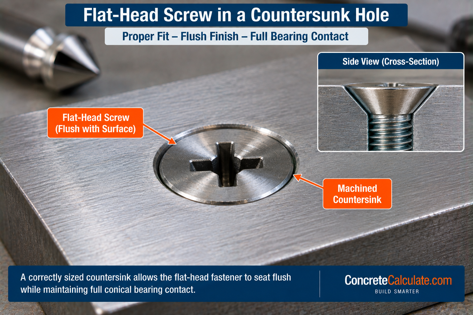
Thin material may not have enough thickness for a full countersink depth. Potential issues include knife-edge holes, deformation, and reduced bearing area. Possible engineered solutions include a dimpled countersink, an undercut fastener, or a different head type. Do not countersink thin sheet blindly.
Undercut Countersunk Screws
An excellent technical differentiator.
ASME B18.6.3 includes undercut 82° flat countersunk-head screws. They provide countersunk head geometry with reduced head height, making them useful where material thickness limits a full standard head recess. Exact dimensions must be taken from the applicable standard table or manufacturer product data.
Countersinks in Thick Plate
More straightforward than thin sheet, but still requires dimensional control.
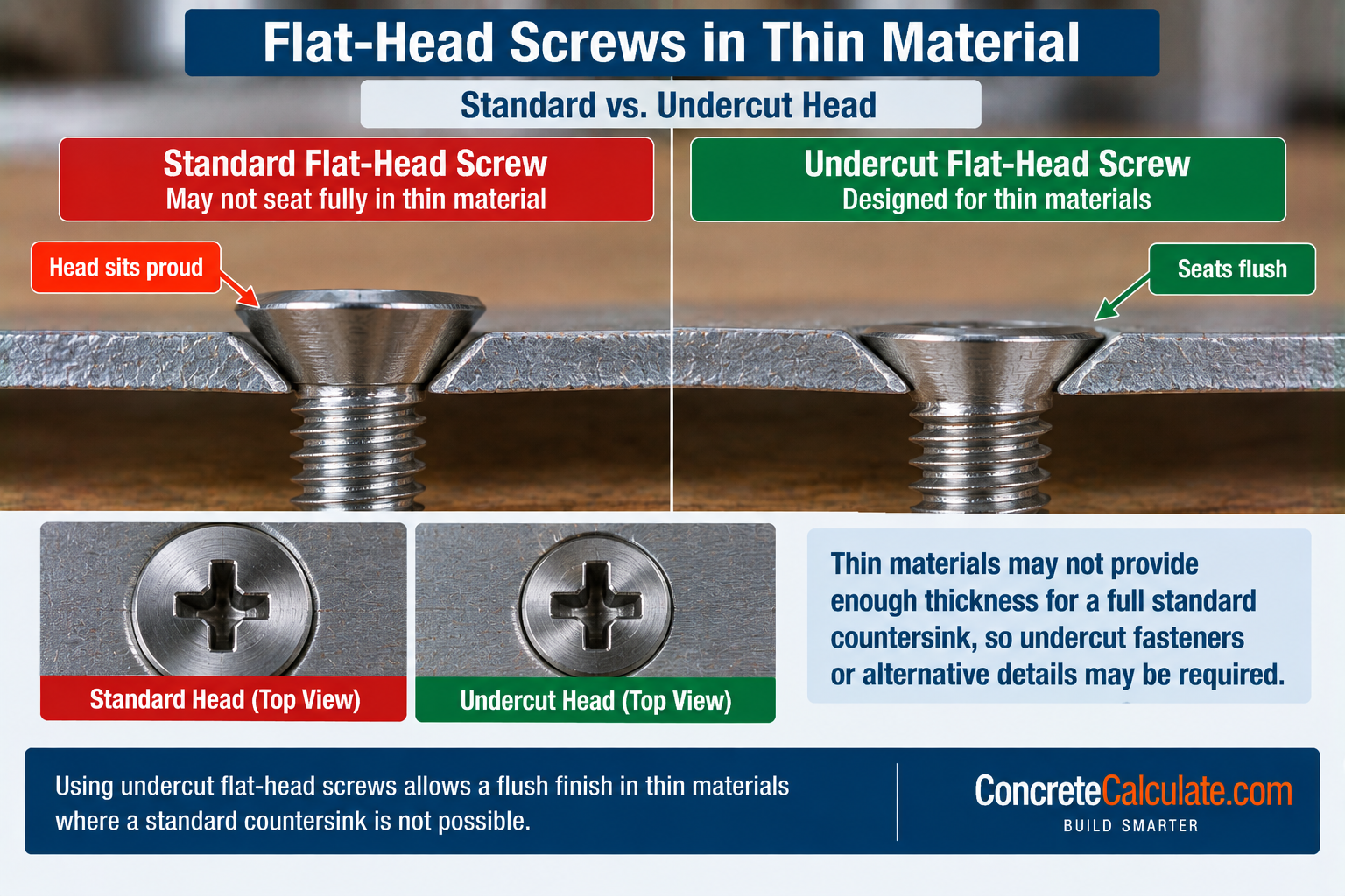
In thick plate, a standard machined countersink is generally more straightforward because adequate material thickness can support a full bearing surface. Still check concentricity, target seating, actual head geometry, and drawing tolerance.
Countersink Tool Angle vs Fastener Angle
The tool must match the required fastener head angle.
| Fastener Head | Required Tool Angle |
|---|---|
| 82° screw | 82° cutter |
| 90° metric screw | 90° cutter |
| 100° aerospace screw | 100° cutter |
ISO 3294 covers tooling at 60°, 90°, and 120°, while other tooling standards and products cover additional angles. Do not assume any general countersink bit is correct for every fastener.
Countersink Tool Types and Deburring
Practical machining section.
Common countersink tool styles include single-flute, multi-flute, and zero-flute or deburring tools. Chatter, finish, material type, and machine rigidity all affect tool selection. A countersink-style tool may be used for deburring, but deburring usually creates only a small edge break; a true countersink is dimensioned for fastener seating.
Countersunk Rivets and 100° Aerospace Countersinks
Keep rivet countersinks separate from screw tables.
Aerospace rivets often use 100° countersunk heads. Active standards such as NASM20426 and NASM20427 cover 100° countersunk rivet forms. Do not apply screw-head countersink dimensions automatically to rivets, even when the included angle appears similar.
How to Measure an Existing Countersink
A useful technical calculation.
Existing Countersink Measurement Workflow
How to Choose the Correct Countersink Size
Practical selection workflow.
Countersink Selection Workflow
Common Countersink Size Mistakes
Assuming every flat-head screw uses 90°
Many U.S. machine screws use 82°, while aerospace forms often use 100°.
Using a 90° cutter on an 82° screw
Angle mismatch creates improper conical contact.
Choosing countersink from screw diameter only
Actual head diameter and head angle must both be known.
Confusing clearance-hole size with countersink diameter
The clearance hole is smaller; countersink diameter receives the head.
Confusing countersink with counterbore
A countersink is conical while a counterbore is cylindrical with a flat bottom.
Cutting too deep
Over-countersinking leaves the head recessed and can reduce bearing surface.
Creating knife-edge holes in thin sheet
Thin material may require undercut fasteners or alternative details.
Assuming rivet countersinks equal screw countersinks
Rivets have their own standards and head geometries.
Treating calculated depth as production tolerance
Geometry output is not a drawing tolerance or acceptance range.
Countersink Size Chart Limitations
Read before countersinking
Countersink diameter depends on fastener head geometry, and countersink angle must match fastener head angle. Screw diameter alone does not determine countersink diameter. Clearance-hole size and countersink size are separate, and metric and inch countersunk heads use different standards. 82°, 90°, and 100° forms are not interchangeable. Thin sheet may not support a full countersink, undercut screws have different geometry, and rivet countersinks require their own standards. Tool geometry and manufactured tolerances matter. Final countersinks should follow the applicable screw/product drawing or standard.
Countersink Size FAQs
Download the Countersink Size Chart
Get a printable reference including countersink angle, depth formula, fastener-head matching, and 82°/90°/100° comparison tables for shop or fabrication use.