Concrete Footing Guide 2026: Types, Sizing, and Construction
Concrete Footing Guide
How concrete footings work, the main footing types, what actually determines footing size, and how footings are built and inspected.
Quick Answer
A concrete footing is the widened base of a foundation that spreads the load from a wall, column, or pier over enough soil area to prevent excessive settlement or bearing failure. Footings come in several structural types, including continuous, isolated, combined, and stepped footings, and their required width, thickness, depth, and reinforcement depend on the load being carried, the soil’s bearing capacity, frost conditions, seismic design category, and the applicable building code.
Footing size is not determined by building size alone. There is no single “standard” footing that works for every house, deck, or wall. For detailed dimension tables once you know your soil and loading conditions, see the Footing Size Chart.
In This Guide
- What Is a Concrete Footing?
- How Does a Concrete Footing Work?
- Why Are Concrete Footings Important?
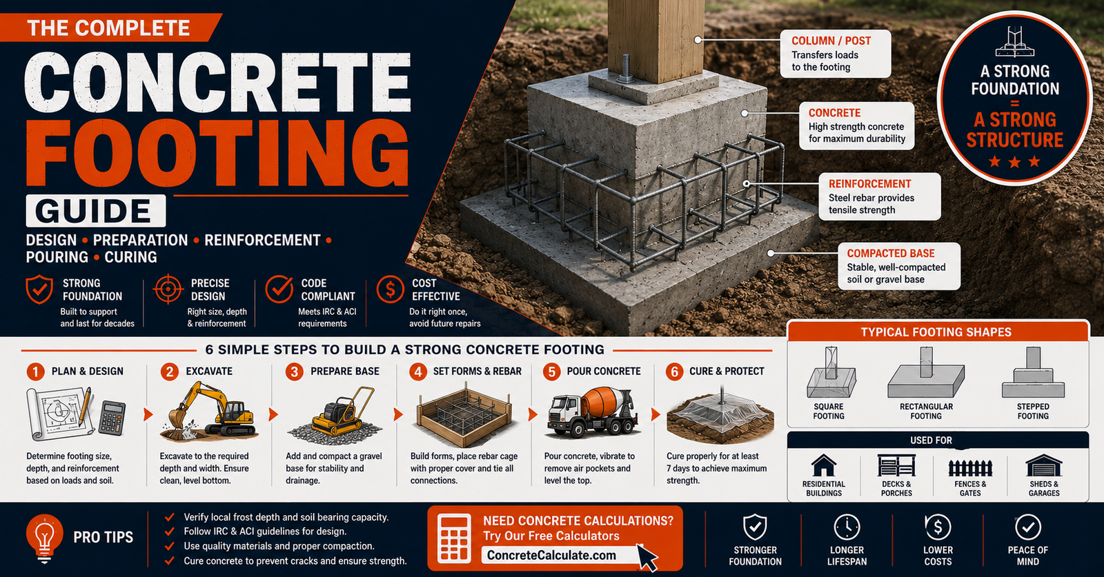
- Concrete Footing Anatomy
- Types of Concrete Footings
- What Determines Concrete Footing Size?
- Concrete Footing Width
- Concrete Footing Thickness
- Concrete Footing Depth
- How Soil Bearing Capacity Affects Footing Size
- How Frost Depth Affects Concrete Footing Depth
- Concrete Footing Requirements Under the IRC
- Concrete Footing Reinforcement and Rebar
- Concrete Cover for Footing Reinforcement
- What Concrete Strength Is Used for Footings?
- Concrete Footings for Different Applications
- Concrete Footing vs. Foundation Wall vs. Slab
- How to Prepare Soil for a Concrete Footing
- How to Excavate for a Concrete Footing
- How to Build and Set Footing Forms
- How to Place Reinforcement in a Concrete Footing
- How to Pour a Concrete Footing
- How to Consolidate and Finish Footing Concrete
- How to Cure Concrete Footings
- How to Calculate Concrete for a Footing
- Concrete Footing Volume Calculation Example
- Concrete Footing Cost
- Common Concrete Footing Problems and Mistakes
- When Should a Concrete Footing Be Designed by an Engineer?
- Concrete Footing Inspection and Pre-Pour Checklist
- Concrete Footing FAQs
What Is a Concrete Footing?
A concrete footing is a widened concrete element placed at the base of a foundation to spread structural loads over enough soil area to keep the building stable. Footings sit below foundation walls, columns, or piers, and they are typically the first concrete element placed in a foundation system. ACI’s residential concrete guidance treats footings as part of a broader foundation system, covering the supporting soil, forms, reinforcement, placement, consolidation, and curing as connected parts of the same construction process, not an isolated concrete pour.
How Does a Concrete Footing Work?
A footing works by transferring structural load through a defined path, from the building down into the supporting soil:
The Load Path
Building loads (roof, floor, walls) → foundation wall, post, or column → concrete footing → supporting soil
The footing’s job is to spread the concentrated or linear load arriving from above over a wide enough soil area that the pressure the soil actually experiences stays within what that soil can safely support. A narrow foundation wall resting directly on soil would apply far more pressure per square foot than that same wall resting on a footing several inches wider, which is the entire structural reason footings exist.
Why Are Concrete Footings Important?
Footings matter because they directly control how a structure interacts with the ground beneath it. An undersized or poorly built footing can lead to excessive settlement, differential movement between different parts of a structure, cracking in walls and slabs above, and in serious cases, structural distress. A properly sized and constructed footing, built on suitable bearing soil, is what keeps those loads distributed safely over time rather than concentrating stress in ways the soil cannot handle.
Concrete Footing Anatomy
Types of Concrete Footings
Most footings fall into a handful of structural categories. Rather than covering dozens of project types individually, understanding these core categories lets you recognize which one applies to almost any footing you’ll encounter.
Continuous and Strip Footings
A continuous or strip footing runs beneath a continuous wall or line load, most commonly a foundation wall or a load-bearing masonry wall. It distributes the wall’s load evenly along its length rather than at isolated points.
Isolated and Spread Footings
An isolated or spread footing supports a single concentrated load, typically from a column or pier. It’s essentially a footing sized to distribute one point load over an appropriate soil area.
Combined Footings
A combined footing supports two or more columns on a single footing, which becomes useful when columns are placed close together or when property-line constraints create eccentric loading that a single isolated footing couldn’t handle well on its own.
Stepped Footings
On sloped sites, a stepped footing changes elevation in defined steps to maintain proper footing depth and bearing conditions across a grade change, rather than running one continuous footing at a constant elevation across sloping ground. The 2024 IRC’s stepped footing provisions specify minimum horizontal step lengths and maximum step rise-to-run ratios, and require additional horizontal reinforcement through step transitions in higher seismic design categories to tie the stepped sections into one structural unit.
Mat Foundations and Other Footing Systems
A mat or raft foundation is a much larger foundation system, essentially one continuous slab-like footing supporting many columns or walls across a large area, typically used where soil conditions are weak or where structural loads are unusually heavy. This is a fundamentally different scale of design than a typical residential strip footing and should not be treated as an extension of ordinary residential footing sizing.
What Determines Concrete Footing Size?
Footing size is one of the most searched footing questions, and it deserves a direct, honest answer: size is not determined by building size alone. It depends on the load being transferred, the allowable soil bearing capacity, the footing type, frost conditions, seismic design category, and applicable code or design requirements working together.
The Conceptual Relationship
A simplified way to think about required footing area:
A ≈ P ÷ qallow
Where A is the required bearing area, P is the design load transferred to the footing, and qallow is the allowable soil bearing pressure. For a continuous wall footing, this relationship is typically applied on a load-per-unit-length basis rather than as a single point-load calculation.
Don’t Design a Footing From This Formula Alone
This conceptual relationship explains why footing size responds to load and soil bearing capacity, but it is not a substitute for an actual structural design. Real design loads, load combinations, soil testing, and applicable code provisions all factor into a properly engineered or prescriptively code-compliant footing. Use the Footing Size Chart for detailed reference dimensions once your project’s loading and soil conditions are known, and consult a design professional for anything outside standard prescriptive conditions.
Concrete Footing Width
Footing width is the dimension most directly tied to the load-per-unit-length and soil bearing relationship above. Under the 2024 IRC’s prescriptive tables for conventional light-frame construction, minimum footing width scales with the number of stories supported and the load-bearing value of the soil. As one illustration of how this works: a one-story building on 1,500 psf soil requires a minimum 12-inch-wide footing, while a two-story building on that same soil requires 15 inches, and a three-story building requires 23 inches, with all of these minimums decreasing as the assumed soil bearing value increases. These figures apply specifically to the IRC’s prescriptive light-frame tables and default soil-bearing assumptions. They are not universal numbers that apply to every wall, every soil, or every jurisdiction, since local amendments and actual project conditions can change the required width.
Concrete Footing Thickness
The 2024 IRC establishes a minimum footing thickness of 6 inches for prescriptive light-frame residential footings, paired with the minimum 12-inch width discussed above, subject to the applicable tables and provisions for the specific construction type. A code minimum, though, is not automatically the correct structural design for every footing. Required thickness can increase because of higher loads, greater footing width or projection beyond the supported wall or column, reinforcement requirements, soil conditions, or a specific structural design that calls for more than the prescriptive minimum.
Concrete Footing Depth
Footing depth actually involves two separate considerations that are frequently blurred together in generic online advice: a general bearing-surface requirement, and frost protection.
12 Inches Is Not a Universal Footing Depth
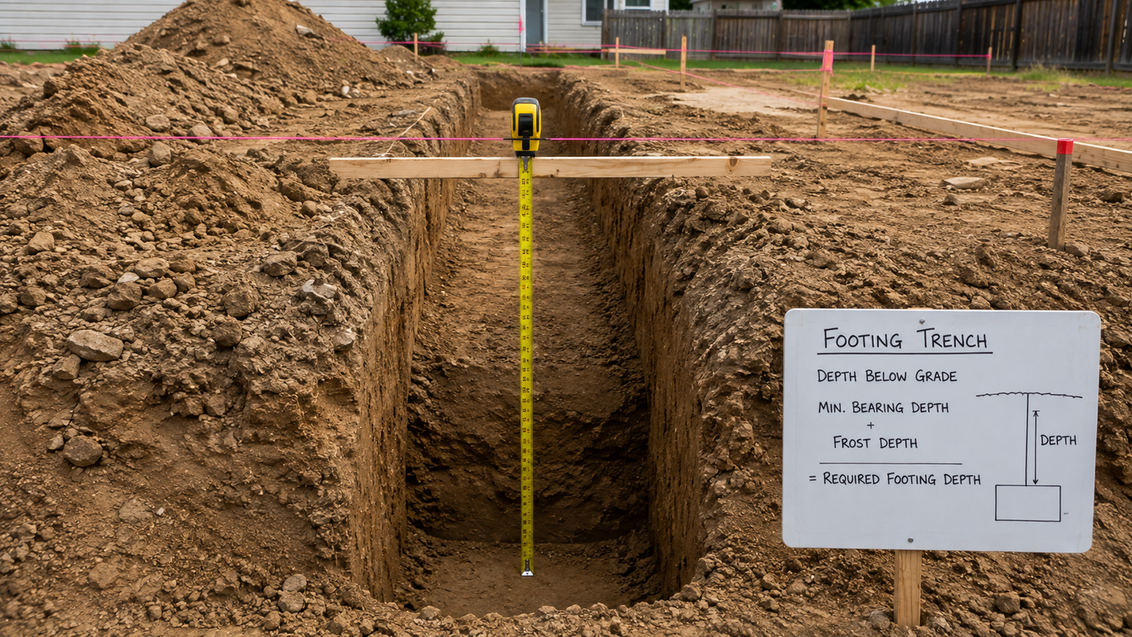
The 2024 IRC requires exterior footings to be placed not less than 12 inches below the undisturbed ground surface. That is the baseline bearing-surface requirement, intended to ensure the footing rests on stable, undisturbed soil rather than loose topsoil or disturbed fill. Separately, footings must also satisfy frost-protection provisions, which commonly require going deeper than 12 inches, sometimes considerably deeper, depending on the local frost depth established by the jurisdiction. Whichever of these two depths is greater is the one that governs.
Frost depth varies significantly across the United States and is set locally, not nationally, which is why the IRC references locally adopted frost-depth tables rather than a single number. In some warmer climates, frost protection may not apply at all, or footings may qualify for frost-protected shallow foundation methods that don’t require excavating to the full conventional frost depth. Always confirm both the 12-inch minimum and the applicable local frost depth for your specific jurisdiction before finalizing footing depth.
How Soil Bearing Capacity Affects Footing Size
Soil bearing capacity is the load-bearing value of the soil beneath the footing, expressed in pounds per square foot (psf), and it has a direct, inverse relationship with required footing width under the IRC’s prescriptive approach.
| Soil Condition | General Bearing Characteristic |
|---|---|
| Dense granular soil (gravel, well-compacted sand) | Generally higher bearing capacity |
| Stiff clay | Can provide moderate to good bearing capacity depending on conditions |
| Loose sand | Generally lower, more variable bearing capacity |
| Soft clay | Generally lower bearing capacity, may require larger footings or engineered solutions |
| Organic soil | Generally unsuitable for direct bearing without remediation |
| Uncontrolled fill | Unpredictable, generally requires evaluation before use as bearing soil |
| Expansive soil | Bearing behavior complicated by moisture-related volume change |
| Rock | Generally very high bearing capacity |
These are general characteristics, not specific psf values, since actual bearing capacity for any given soil depends on site-specific testing, moisture conditions, and local geology. The IRC’s prescriptive footing tables use default soil-bearing values of 1,500, 2,000, 3,000, and 4,000 psf and greater as reference columns; actual site soil should be evaluated against those categories by a qualified party where the project requires it.
The general pattern is straightforward: stronger soil can generally support a given load over a smaller bearing area, while weaker soil generally requires either a larger bearing area or a different foundation approach entirely. When soil bearing capacity is uncertain, unusually low, or outside normal residential assumptions, that is a strong signal to involve a geotechnical professional rather than guessing.
How Frost Depth Affects Concrete Footing Depth
In climates where the ground freezes, frost heave, meaning the upward movement of soil as water within it freezes and expands, can move a footing that isn’t founded below the frost line. The IRC addresses this by requiring footings to extend below the locally established frost depth, in addition to meeting the general 12-inch minimum below undisturbed ground. Some jurisdictions also permit frost-protected shallow foundation designs, which use insulation and other design measures to protect against frost heave without excavating to full conventional frost depth. Because frost depth is locally determined and can range from minimal in warm climates to several feet in cold northern regions, always confirm your specific jurisdiction’s adopted frost depth table rather than relying on a generic number found online.
Concrete Footing Requirements Under the IRC
The International Residential Code’s Section R403 is the primary prescriptive reference for residential footings in the United States, though the exact edition and any local amendments adopted by your jurisdiction control in practice. Key areas R403 addresses include:
- Minimum footing width and thickness, based on soil bearing value, number of stories, and construction type
- Minimum footing depth, tied to undisturbed ground and frost protection
- Stepped footings for sloped sites, with specific geometry requirements
- Reinforcement requirements for footings in higher seismic design categories
- Isolated footing provisions for columns and piers
ACI 332, the code covering residential concrete construction, complements the IRC by addressing the broader construction process for footings, including subgrade preparation, forms, reinforcement placement, concrete placement, consolidation, and curing. Since code editions and local amendments vary by jurisdiction, treat any specific figure in this guide as illustrative of how the code approaches the topic, and always confirm current requirements with your local building department.
Concrete Footing Reinforcement and Rebar
Not every footing requires the same reinforcement, and the guide’s job here is to explain the concepts rather than hand out one universal bar schedule. Reinforcement in footings can serve several purposes:
- Longitudinal reinforcement, running the length of a continuous footing to help control cracking and tie the footing together as a unit
- Transverse reinforcement, used where a structural design calls for it, such as in wider or more heavily loaded footings
- Dowels, connecting the footing to a stem wall or column above it
- Column and pier connections, which may require specific reinforcement detailing to transfer load properly into the footing
- Chairs and supports, used to hold reinforcement at the correct height and cover during the pour
- Concrete cover, protecting the reinforcement from corrosion and environmental exposure
- Development length and lap splices, ensuring reinforcing bars are properly anchored or connected to each other
Seismic Design Categories Change the Requirements
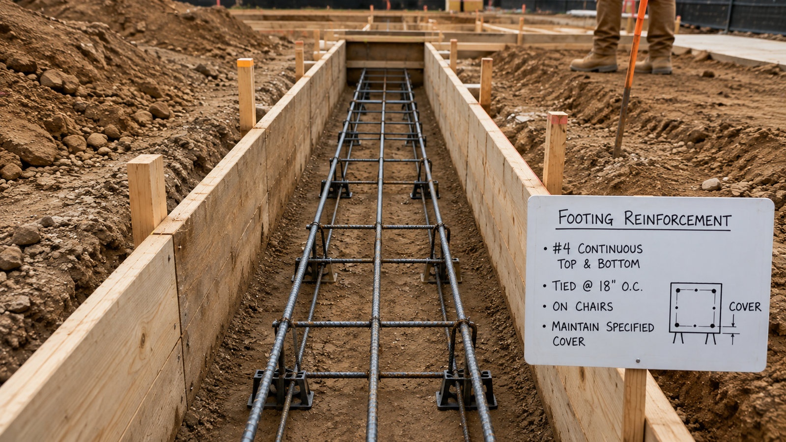
The IRC specifically requires reinforcement in footings located in Seismic Design Categories D0, D1, and D2, commonly calling for a minimum of two continuous horizontal reinforcing bars, positioned near the top and bottom of the footing, along with additional detailing at stem wall connections in some configurations. Outside those higher seismic categories, the IRC’s prescriptive footing tables may permit plain, unreinforced concrete footings when the standard dimensional requirements are met. This means whether your footing needs rebar at all, and how much, depends heavily on your specific location’s seismic design category, not a one-size-fits-all rule like “every footing needs two number four bars.”
For actual bar sizing, grade selection, and splice-length reference information, see the Rebar Size Chart, Rebar Grade Chart, and Rebar Lap Splice Chart. For the broader question of whether a given concrete element needs reinforcement at all, see Does Concrete Need Rebar?
Concrete Cover for Footing Reinforcement
Footings cast against earth face a different exposure environment than reinforced concrete formed and finished indoors, which is why they typically require greater concrete cover over the reinforcing steel. The specific cover requirement should always come from the applicable design standard or code provision governing your project, particularly for concrete cast directly against soil. Rather than treating one cover value as a universal figure, position reinforcement using the cover specified by the applicable design and code requirements for your project’s exposure condition. For a complete reference on cover requirements across different exposure conditions, see the Concrete Cover Chart.
What Concrete Strength Is Used for Footings?
Concrete compressive strength for a footing is specified by the project’s design and applicable code, not chosen from a generic assumption about what footings “normally” use. Appropriate strength depends on the structural loads involved, environmental exposure such as freeze-thaw cycling, durability requirements for the local climate, and any project-specific specifications. Rather than repeating strength figures here, see the Concrete PSI Guide for a complete discussion of how compressive strength is specified and selected.
Concrete Footings for Different Applications
| Application | Common Footing Concept | Design Dependency |
|---|---|---|
| Residential house | Continuous wall footing | Load, soil bearing, applicable code |
| Garage | Perimeter footing, possibly interior support | Design, loads, soil |
| Deck | Isolated pier/footing | Tributary load, frost depth, applicable code |
| Porch | Point or continuous footing | Design configuration |
| Shed | Varies widely by size and construction | Size, soil, local requirements |
| Retaining wall | Spread footing with stability design | Overturning, sliding, bearing, drainage, soil pressure |
| Column | Isolated footing/pad | Tributary load, soil bearing |
| Fence | Post or pier footing | Post loading, frost depth, local code |
A retaining wall footing deserves particular caution: it must resist overturning and sliding forces from retained soil pressure in addition to ordinary bearing loads, and should not be treated as an ordinary house footing scaled up or down.
Concrete Footing vs. Foundation Wall vs. Slab
| Element | Primary Role |
|---|---|
| Footing | Transfers and distributes structural loads into the supporting soil |
| Foundation wall | Transfers loads from the structure above down to the footing |
| Stem wall | A short foundation wall built above a footing, common in crawlspace and slab construction |
| Slab | A floor or ground-supported structural element; not automatically a substitute for a properly designed footing |
How to Prepare Soil for a Concrete Footing
Footing bearing soil and general slab subgrade are related concepts, but they are not identical design conditions. A slab typically distributes light, relatively uniform surface loads, while a footing concentrates significant structural load onto a smaller area, which means the bearing surface beneath a footing deserves particular scrutiny. For the complete discussion of organic material removal, grading, soft-spot correction, and compaction principles that also apply to footing bearing soil, see How to Prepare Soil for a Concrete Slab.
How to Excavate for a Concrete Footing
A footing is only as good as the surface it bears on. During and after excavation, confirm the bearing surface is free of:
- Loose or disturbed soil that hasn’t been properly compacted
- Standing water or visibly saturated soil
- Mud or slurry conditions at the base of the excavation
- Organic material, including roots and topsoil
- Uncontrolled or undocumented fill
- Any other disturbed bearing material that doesn’t match the design’s assumed soil condition
The bottom of the excavation should also be level and at the correct elevation, so the footing bears evenly across its entire base rather than resting unevenly on high points.
How to Build and Set Footing Forms
Footing layout establishes where the entire foundation system will sit, so accuracy here matters more than almost any other step. Layout typically involves:
- Marking footing centerlines and wall lines from the project’s plans
- Establishing column or pier centers accurately
- Confirming everything sits at the correct distance from property lines
- Squaring corners precisely, since small layout errors compound around a building’s perimeter
- Accounting for any steps or offsets required by grade changes
- Verifying elevation at multiple points before forms are finalized
Once layout is confirmed, forms need to be square, plumb, adequately braced, and set to the correct elevation and width, since forms that shift during placement will produce an inconsistent footing.
How to Place Reinforcement in a Concrete Footing
Where reinforcement is required, it needs to be positioned according to the project’s design, supported on chairs or bolsters to maintain the specified cover, and checked for correct spacing and continuity, particularly at corners and intersections where reinforcement continuity is often specifically required. Verify bar size, spacing, and position against the design documents before concrete arrives, since reinforcement is far easier to correct before the pour than after.
How to Pour a Concrete Footing
Before concrete is placed, the excavation, forms, and reinforcement should already be inspected and verified against the checklist covered later in this guide. Concrete should be placed continuously where practical, avoiding excessive drop heights that can cause segregation, and worked into corners and around reinforcement to avoid voids.
How to Consolidate and Finish Footing Concrete
Consolidation removes trapped air and works the concrete tightly around reinforcement and into the corners of the form, which is essential for avoiding honeycombing and voids. Footings are typically struck off level at the top, since a flat, level footing surface is important for whatever foundation wall or structural element will be built on top of it next.
How to Cure Concrete Footings
Like any concrete element, footings need proper curing to develop their intended strength and durability. Curing requirements and appropriate timelines vary by concrete mix, weather conditions, and project specifications. See the Concrete Curing and Drying Time Guide and Concrete Curing Time Chart for a complete discussion. Backfilling against a footing or adjacent foundation wall should only happen once the concrete has reached adequate strength for that loading, per the project specification.
How to Calculate Concrete for a Footing
For a rectangular footing, the concrete volume formula is straightforward:
Footing Volume Formula
V = L × W × T
Where L is footing length, W is footing width, and T is footing thickness. For a continuous footing, use the total footing length along the wall or foundation line.
Convert to ready-mix ordering units with: Cubic yards = Cubic feet ÷ 27
For a complete walkthrough of unit conversions and the broader concrete calculation framework, see How to Calculate Concrete.
Concrete Footing Volume Calculation Example
Worked Example: 60-Foot Continuous Footing
Given: A continuous footing 60 ft long, 1.5 ft (18 in) wide, and 0.5 ft (6 in) thick.
Calculation: 60 × 1.5 × 0.5 = 45 ft³
Convert to cubic yards: 45 ÷ 27 ≈ 1.67 yd³
What it means: This is the net calculated volume for this specific hypothetical footing geometry. Actual ordering quantities should account for the real project’s exact dimensions and a reasonable ordering allowance for site conditions, not simply this calculated figure alone.
| Footing Length | Width × Thickness (example) | Approx. Volume |
|---|---|---|
| 10 ft | 1.5 ft × 0.5 ft | 7.5 ft³ (≈ 0.28 yd³) |
| 20 ft | 1.5 ft × 0.5 ft | 15 ft³ (≈ 0.56 yd³) |
| 40 ft | 1.5 ft × 0.5 ft | 30 ft³ (≈ 1.11 yd³) |
| 60 ft | 1.5 ft × 0.5 ft | 45 ft³ (≈ 1.67 yd³) |
These examples use a clearly stated hypothetical 18-inch by 6-inch footing for illustration only. Your actual footing width and thickness must come from your project’s design or applicable code table.
For your actual project dimensions, use the Concrete Footing Calculator, and once you have a total volume, cross-check it against How Many Yards of Concrete Do I Need?
Concrete Footing Cost
Footing cost varies substantially by project scope and region, so a single universal cost-per-linear-foot figure would be misleading. Common cost components include:
- Excavation and equipment
- Formwork materials and labor
- Reinforcing steel
- Concrete material and delivery
- Pumping, if required for access
- General labor
- Compaction and material testing where required
- Inspection fees
- Drainage-related work
- Site access considerations
- Engineering, for projects requiring professional design
For a fuller cost breakdown tied to a complete foundation system, see the Concrete Foundation Cost Guide.
Common Concrete Footing Problems and Mistakes
| Problem | Potential Consequence |
|---|---|
| Undersized footing | Excessive soil pressure, increased settlement risk |
| Poor bearing soil | Differential settlement |
| Incorrect depth | Frost-related movement |
| Misplaced reinforcement | Reduced structural performance |
| Insufficient cover | Corrosion and durability risk |
| Poor consolidation | Voids or honeycombing |
| Poor drainage | Water intrusion and foundation problems |
Beyond this table, watch for pouring on frozen or saturated ground, skipping bearing-surface inspection before the pour, assuming a footing size from a competing website without checking your actual soil and code conditions, and beginning backfill before the concrete has reached adequate strength.
When Should a Concrete Footing Be Designed by an Engineer?
The 2024 IRC provides prescriptive footing provisions specifically for conditions within its assumptions, conventional light-frame residential construction, typical soil bearing values, and standard seismic categories. Projects that fall outside those assumptions generally need professional design. Consider a structural or geotechnical engineer when your project involves:
- Commercial or non-residential structures
- Significant point loads outside typical residential ranges
- Poor, unusual, or unknown soil conditions
- Expansive soil
- Uncontrolled or undocumented fill
- Unusual foundation geometry
- Retaining structures
- Steep slopes
- High groundwater
- Seismic conditions requiring engineered design beyond prescriptive provisions
- Structures that fall outside prescriptive residential code provisions
- Evidence of significant existing settlement
- Unusual or non-standard loading conditions
| Issue | Typically Responsible Party |
|---|---|
| Standard prescriptive residential footing | Contractor, following applicable code tables |
| Soil bearing evaluation | Geotechnical professional |
| Non-prescriptive or unusual footing design | Structural engineer |
| Field density/compaction verification | Testing agency |
| Code compliance approval | Local building department |
This does not mean every backyard shed footing needs an engineer. It means that when your project falls outside the prescriptive code’s assumptions, or the consequences of getting it wrong are significant, professional input is the responsible next step.
Concrete Footing Inspection and Pre-Pour Checklist
Before You Pour
- Layout verified against plans, including corners, offsets, and property line clearances
- Excavation reaches the required depth and undisturbed or properly prepared bearing soil
- Bearing surface free of loose soil, standing water, mud, or organic material
- Footing width and thickness match the design or applicable code table
- Forms square, plumb, properly braced, and set to correct elevation
- Reinforcement, where required, positioned with correct size, spacing, and cover
- Dowels or connections for stem walls, columns, or piers correctly placed
- Utility conduits or sleeves through the footing coordinated in advance, not cut afterward
- Required inspections completed and approved before concrete placement
Concrete Footing FAQs
What is a concrete footing?
A concrete footing is a widened base element at the bottom of a foundation that spreads structural loads over enough soil area to prevent excessive settlement or bearing failure.
What is the purpose of a concrete footing?
Its purpose is to transfer loads from the structure above, through the foundation, into the supporting soil at a pressure the soil can safely handle.
How does a concrete footing work?
It works by distributing concentrated or linear loads over a wider area of soil than the wall or column above it alone would cover, reducing the pressure the soil experiences at any single point.
How deep should a concrete footing be?
Exterior footings must generally be at least 12 inches below undisturbed ground, and must also satisfy the locally established frost depth, whichever requirement is deeper. There is no single universal footing depth for every location.
How wide should a concrete footing be?
Footing width depends on the load being carried and the soil’s bearing capacity. Prescriptive residential tables scale minimum width with the number of stories and the assumed soil bearing value; actual required width should come from your project’s applicable code table or design.
How thick should a concrete footing be?
Many prescriptive residential footings use a 6-inch minimum thickness, but actual required thickness can increase based on loads, footing width, reinforcement, and project-specific design.
What size concrete footing do I need?
The correct size depends on your specific loads, soil bearing capacity, footing type, frost conditions, and applicable code. See the Footing Size Chart for detailed reference dimensions once those conditions are known.
How much concrete do I need for a footing?
Multiply footing length by width by thickness to get cubic feet, then divide by 27 for cubic yards. See the worked example in this guide and the Concrete Footing Calculator for your specific dimensions.
Does a concrete footing need rebar?
It depends on your seismic design category and applicable code. Some jurisdictions require reinforcement in higher seismic design categories, while prescriptive footings in lower categories may be built without it when standard dimensional requirements are met.
What type of concrete is used for footings?
The required compressive strength is specified by the project design and applicable code based on structural loads and environmental exposure, not a single universal mix used for every footing.
What goes under a concrete footing?
Properly prepared, undisturbed, or compacted bearing soil, free of organic material, debris, and excess moisture, with the footing bearing directly on that prepared surface.
Concrete footing vs. foundation: what’s the difference?
A footing is the base element that spreads load into the soil, while the foundation, including any foundation or stem wall, transfers the building’s loads down to that footing. The footing is part of the overall foundation system.
Concrete footing vs. slab: what’s the difference?
A footing distributes concentrated structural loads into the soil at specific locations, while a slab is a broader floor or ground-supported element. A slab is not automatically a substitute for a properly designed footing.
What is a continuous concrete footing?
A continuous footing runs beneath a continuous wall or line load, distributing that load evenly along its length, most commonly used beneath foundation walls.
What is an isolated concrete footing?
An isolated or spread footing supports a single concentrated load, typically from a column or pier, distributing that point load over an appropriately sized area of soil.
Ready to Size Your Footing?
Once you know your loads and soil conditions, use the Footing Size Chart for detailed dimension tables, then calculate your concrete quantity.
View the Footing Size Chart