Tap Drill Chart 2026 – UNC, UNF & Metric Drill Sizes
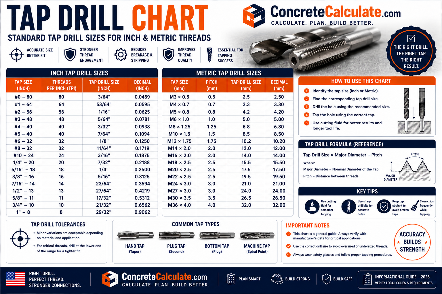
Tap Drill Chart
UNC, UNF & Metric Drill Sizes
Tap drill selection depends on thread, pitch, desired thread engagement, and tap type. Every table here states its calculation basis rather than a bare recommended drill.
 Reviewed by Muhammad Ramzan Babar, PhD Researcher & Calculator Developer · View Profile
Every drill size in this chart states its thread designation, pitch/TPI, calculated diameter, thread engagement basis, and tap type. Do not assume 75 percent thread is universally required; actual desired engagement depends on material, tap type, application and manufacturer recommendations. Cutting taps and forming taps use different drill-size formulas, covered separately below.
⭐ Tap Drill Chart: Quick Reference
Values below use the cutting tap formula at approximately 75 percent thread engagement, a common general purpose reference basis. Forming tap and other engagement percentages are covered in dedicated sections.
| Thread Size | Thread Type | Pitch/TPI | Calculated Drill (in) | Nearest Standard Drill | Decimal (in) |
|---|---|---|---|---|---|
| 1/4-20 | UNC | 20 TPI | 0.2013 | #7 | 0.2010 |
| 5/16-18 | UNC | 18 TPI | 0.2584 | Letter F | 0.2570 |
| 3/8-16 | UNC | 16 TPI | 0.3141 | 5/16 in | 0.3125 |
| 1/2-13 | UNC | 13 TPI | 0.4251 | 27/64 in | 0.4219 |
| M6 x 1.0 | Metric | 1.0 mm | 5.00 mm | 5.0 mm | 0.1969 |
| M8 x 1.25 | Metric | 1.25 mm | 6.75 mm | 6.8 mm | 0.2677 |
| M10 x 1.5 | Metric | 1.5 mm | 8.50 mm | 8.5 mm | 0.3346 |
| M12 x 1.75 | Metric | 1.75 mm | 10.25 mm | 10.2 or 10.3 mm | 0.4016 to 0.4055 |
The calculated theoretical diameter rarely matches an off-the-shelf drill exactly. Standard number, letter, fractional and metric drill sizes are selected as the nearest available size to the calculated value, which is why the two columns differ slightly.
⭐ What Is a Tap Drill?
A tap drill creates the pilot hole into which a tap cuts or forms an internal thread.
Pilot hole
The drilled hole made before tapping, sized smaller than the thread’s major diameter to leave material for the tap to engage.
Tapped hole
The finished internal thread created after the tap passes through the pilot hole, forming the female thread that mates with a bolt or screw.
Internal thread
The thread cut or formed inside the hole, as opposed to the external thread on a bolt.
Thread engagement
How much of the theoretical full thread height is actually present in the finished tapped hole, controlled directly by the pilot hole diameter.
⭐ Tap Drill Size vs Tap Size
This distinction prevents one of the most common tapping mistakes.
A 1/4-20 tap does not mean drilling a 1/4 inch hole. The drill must be smaller than the tap’s major diameter so the tap has material remaining to cut or form the internal thread. For 1/4-20 at approximately 75 percent engagement, the correct drill is closer to 0.201 inches, commonly a number 7 drill, not 0.250 inches.
The tap’s designation (such as 1/4-20 or M8 x 1.25) states the finished thread’s major diameter and pitch, not the drill size needed to create that thread.
⭐ UNC Tap Drill Chart
Calculated using the cutting tap formula: drill diameter equals major diameter minus (0.01299 times desired percent of thread, divided by TPI), at 75 percent thread engagement.
| UNC Thread | TPI | Calculated Drill at 75% (in) | Nearest Standard Drill |
|---|---|---|---|
| #0-80 | 80 | 0.0478 | #55 |
| #1-64 | 64 | 0.0578 | #53 |
| #2-56 | 56 | 0.0686 | #50 |
| #3-48 | 48 | 0.0787 | #47 |
| #4-40 | 40 | 0.0876 | #43 |
| #5-40 | 40 | 0.1006 | #38 |
| #6-32 | 32 | 0.1076 | #36 |
| #8-32 | 32 | 0.1336 | #29 |
| #10-24 | 24 | 0.1494 | #25 |
| #12-24 | 24 | 0.1754 | #16 |
| 1/4-20 | 20 | 0.2013 | #7 |
| 5/16-18 | 18 | 0.2584 | Letter F |
| 3/8-16 | 16 | 0.3141 | 5/16 in |
| 7/16-14 | 14 | 0.3679 | Letter U |
| 1/2-13 | 13 | 0.4251 | 27/64 in |
| 9/16-12 | 12 | 0.4813 | 31/64 in |
| 5/8-11 | 11 | 0.5364 | 17/32 in |
| 3/4-10 | 10 | 0.6526 | 21/32 in |
| 7/8-9 | 9 | 0.7668 | 49/64 in |
| 1-8 | 8 | 0.8782 | 7/8 in |
Drill diameter (in) = Major diameter minus [(0.01299 x desired percent of thread) divided by TPI]. This is a widely published cutting-tap formula for Unified inch threads; slightly different specific commercial drill sizes may appear across various published references due to rounding and available stock sizes.
⭐ UNF Tap Drill Chart
UNC and UNF tables are kept separate because they use different TPI at the same nominal diameter.
| UNF Thread | TPI | Calculated Drill at 75% (in) |
|---|---|---|
| #0-80 | 80 | 0.0478 |
| #1-72 | 72 | 0.0595 |
| #2-64 | 64 | 0.0708 |
| #3-56 | 56 | 0.0816 |
| #4-48 | 48 | 0.0917 |
| #5-44 | 44 | 0.1029 |
| #6-40 | 40 | 0.1136 |
| #8-36 | 36 | 0.1369 |
| #10-32 | 32 | 0.1596 |
| #12-28 | 28 | 0.1812 |
| 1/4-28 | 28 | 0.2152 |
| 5/16-24 | 24 | 0.2719 |
| 3/8-24 | 24 | 0.3344 |
| 7/16-20 | 20 | 0.3888 |
| 1/2-20 | 20 | 0.4513 |
| 9/16-18 | 18 | 0.5084 |
| 5/8-18 | 18 | 0.5709 |
| 3/4-16 | 16 | 0.6891 |
| 7/8-14 | 14 | 0.8054 |
| 1-12 | 12 | 0.9188 |
Compare 1/4-20 UNC (drill approximately 0.201 in) against 1/4-28 UNF (drill approximately 0.215 in) at the same 75 percent engagement basis. UNF’s finer pitch and higher TPI require a larger pilot hole than UNC at the identical nominal diameter, because less material needs to be removed to reach the same percentage of a shallower thread.
⭐ Metric Tap Drill Chart
Metric cutting tap drills are commonly approximated as major diameter minus pitch, closely corresponding to roughly 75 percent thread engagement.
| Metric Thread | Pitch (mm) | Cutting Tap Drill (mm) | Forming Tap Drill (mm) |
|---|---|---|---|
| M3 x 0.5 | 0.5 | 2.50 | 2.75 |
| M4 x 0.7 | 0.7 | 3.30 | 3.65 |
| M5 x 0.8 | 0.8 | 4.20 | 4.60 |
| M6 x 1.0 | 1.0 | 5.00 | 5.50 |
| M8 x 1.25 | 1.25 | 6.75 | 7.38 |
| M10 x 1.5 | 1.5 | 8.50 | 9.25 |
| M12 x 1.75 | 1.75 | 10.25 | 11.12 |
| M14 x 2.0 | 2.0 | 12.00 | 13.00 |
| M16 x 2.0 | 2.0 | 14.00 | 15.00 |
| M18 x 2.5 | 2.5 | 15.50 | 16.75 |
| M20 x 2.5 | 2.5 | 17.50 | 18.75 |
| M24 x 3.0 | 3.0 | 21.00 | 22.50 |
Metric coarse tap drills
Coarse pitch is the standard, most commonly tapped metric pitch for each diameter, as reflected in the table above.
Metric fine tap drills
Fine pitch alternatives (such as M12 x 1.25 or M10 x 1.0) require different drill sizes than their coarse counterparts at the same nominal diameter. Not every diameter has a standardized fine pitch; verify against the Metric Thread Chart before assuming one exists.
Metric cutting tap drill approximately equals major diameter minus pitch. Metric forming tap drill approximately equals major diameter minus (pitch times 0.5), reflecting that forming taps displace rather than remove material and therefore require a larger starting hole.
⭐ What Is Thread Engagement?
Thread engagement describes how much of the theoretical full thread height is actually formed in the tapped hole.
| Thread Engagement | Relative Tapping Difficulty | General Consideration |
|---|---|---|
| 50% | Lower | Reduced torque and breakage risk; may reduce joint strength |
| 60% | Lower to moderate | Common for harder materials or lower-strength requirements |
| 65% | Moderate | Common reference for stainless steel and similar materials |
| 70% | Moderate | Balanced general purpose option |
| 75% | Higher | Widely used general reference basis for many materials |
| 80% | Higher | Used where greater strength is prioritized over ease of tapping |
| 100% | Very high | Theoretical full thread height; rarely used in production due to torque and breakage risk |
These difficulty ratings are general tendencies, not fixed values. Actual tapping torque and thread strength depend heavily on tap geometry, material hardness, lubrication and process conditions, not on engagement percentage alone.
50% vs 75% engagement trade-off
Lower engagement percentages reduce tapping torque and tap breakage risk, at some potential cost to thread strength; higher percentages increase strength potential but raise torque, tool wear and breakage risk, particularly in harder materials.
What “75% thread” actually means
The percentage refers to a defined theoretical thread height basis. Different references do not always express this percentage using identical definitions or rounding conventions, which is why published tap drill charts can show small variations for the same nominal thread.
⭐ Tap Drill Formulas
These formulas calculate a theoretical drill diameter; the nearest available commercial drill is then selected in practice.
| Tap Type | System | Formula |
|---|---|---|
| Cutting tap | Inch (UNC/UNF) | Drill (in) = Major dia. minus [(0.01299 x desired % thread) / TPI] |
| Cutting tap | Metric | Drill (mm) = Major dia. minus [(desired % thread x pitch) / 76.98] |
| Forming tap | Inch | Drill (in) = Major dia. minus [(0.0068 x desired % thread) / TPI] |
| Forming tap | Metric | Drill (mm) = Major dia. minus [(desired % thread x pitch) / 147.06] |
Worked example: 1/4-20 UNC cutting tap at 75%
Drill = 0.250 minus [(0.01299 x 75) / 20] = 0.250 minus 0.0487 = approximately 0.2013 inches, matched to a number 7 drill (0.201 in).
Worked example: M8 x 1.25 cutting tap
Using the simplified approximation drill equals major diameter minus pitch: 8 minus 1.25 = 6.75 mm, commonly rounded to a standard 6.8 mm drill.
These formulas reflect commonly published general purpose relationships for cutting and forming taps. Actual tap manufacturer literature may specify slightly different coefficients or additional adjustments for specific tap geometries, materials, or coatings; always check the manufacturer’s recommendation for critical or high-volume work.
⭐ Cutting Tap vs Forming Tap
These two tap types work fundamentally differently and require different pilot hole sizes for the same finished thread.
| Feature | Cutting Tap | Forming Tap |
|---|---|---|
| Mechanism | Removes material as chips | Displaces material, no cutting chips |
| Required drill size | Smaller pilot hole | Larger pilot hole than cutting tap for the same thread |
| Chip evacuation | Required, especially in blind holes | Not applicable since no chips are produced |
| Thread strength | Standard | Often higher due to cold-worked, unbroken grain structure |
| Suitable materials | Most metals, including harder and more brittle materials | Ductile materials such as aluminum, mild steel, copper alloys; not ideal for brittle materials |
| Typical drill size difference | Baseline | Approximately 0.2 to 0.5 mm larger at common construction sizes (M4 to M12) |
| Thread | Cutting Tap Drill (mm) | Forming Tap Drill (mm) | Difference |
|---|---|---|---|
| M4 x 0.7 | 3.3 | 3.5 to 3.65 | +0.2 to 0.35 |
| M5 x 0.8 | 4.2 | 4.5 to 4.6 | +0.3 to 0.4 |
| M6 x 1.0 | 5.0 | 5.25 to 5.5 | +0.25 to 0.5 |
| M8 x 1.25 | 6.75 to 6.8 | 7.0 to 7.38 | +0.2 to 0.6 |
| M10 x 1.5 | 8.5 | 8.9 to 9.25 | +0.4 to 0.75 |
| M12 x 1.75 | 10.2 to 10.25 | 10.7 to 11.12 | +0.5 to 0.9 |
Using a cutting-tap drill size with a forming tap will leave insufficient material for the tap to properly displace, risking tap breakage or a poorly formed thread. Confirm which tap type is being used before selecting a drill size.
⭐ Tap Drill Size by Material
Material alone does not determine tap drill size; it primarily influences the appropriate thread engagement percentage, tap type, and lubrication strategy.
Mild / carbon steel
Generally tolerant of standard 70 to 75 percent engagement with a cutting tap and conventional cutting oil.
Stainless steel ⭐
Prone to work hardening and galling; often tapped at a lower 50 to 65 percent engagement with appropriate cutting fluid and slower speeds to reduce torque and breakage risk. See the Bolt Torque Chart for related stainless fastener notes.
Aluminum
Soft and gummy; benefits from sharp cutting taps or forming taps, good chip evacuation, and aluminum-specific lubricant to prevent built-up edge and thread tearing.
Brass
Generally machines and taps cleanly; cutting taps with appropriate geometry for brass are commonly used, with attention to thread engagement for the intended joint.
Cast iron
Produces short, brittle chips; typically tapped dry or with minimal lubrication, with attention to chip evacuation in blind holes.
Plastics
Often tolerate a wider range of engagement percentages; specialized plastic taps with appropriate flute design help prevent cracking or melting from friction heat.
Always confirm the tap manufacturer’s specific recommendation for the material and tap coating being used rather than relying on generalized material guidance alone.
Equipment for Your Project
Affiliate disclosure: As an Amazon Associate, ConcreteCalculate earns from qualifying purchases. We may also earn a commission from other affiliate links at no additional cost to you.
⭐ Number, Letter & Fractional Drill Reference
U.S. tap drill charts commonly specify number or letter drills rather than fractional or metric sizes.
| Drill | Decimal (in) | mm |
|---|---|---|
| #7 | 0.2010 | 5.11 |
| #25 | 0.1495 | 3.80 |
| #29 | 0.1360 | 3.45 |
| #36 | 0.1065 | 2.71 |
| Letter F | 0.2570 | 6.53 |
| Letter U | 0.3680 | 9.35 |
| 5/16 in | 0.3125 | 7.94 |
| 27/64 in | 0.4219 | 10.72 |
| 17/32 in | 0.5313 | 13.49 |
| 21/32 in | 0.6563 | 16.67 |
Fractional drills
Sized in inch fractions such as 1/8, 5/32, 3/16, 7/32, 1/4 and larger, commonly used for larger tap drills where a number or letter size is not needed.
Number drills
Sized #1 (largest, 0.2280 in) through #80 (smallest, 0.0135 in), commonly used for small to medium tap drills.
Letter drills
Sized A (0.2340 in) through Z (0.4130 in), filling the gap between the largest number drills and common fractional sizes.
Metric drills
Sized directly in millimeters, commonly in 0.05 or 0.1 mm increments for precision work.
⭐ Tap Drill vs Clearance Drill
These serve opposite purposes and should never be confused.
| Hole Type | Purpose | Relative Size |
|---|---|---|
| Tap drill | Creates a pilot hole for cutting or forming an internal thread | Smaller than the fastener’s major diameter |
| Close clearance hole | Allows a bolt to pass through with minimal side play | Slightly larger than the fastener’s major diameter |
| Normal clearance hole | Allows a bolt to pass through with standard assembly play | Moderately larger than the fastener’s major diameter |
| Loose clearance hole | Allows for significant alignment tolerance or thermal movement | Noticeably larger than the fastener’s major diameter |
Pilot vs tap drill
In some contexts, pilot hole is used interchangeably with tap drill; in others, pilot hole refers to a smaller starting hole drilled before a larger final tap drill for stepped drilling in tougher materials.
Counterbore and countersink
These are secondary machining operations that create a recess for a fastener head, separate from both the tap drill and clearance hole functions.
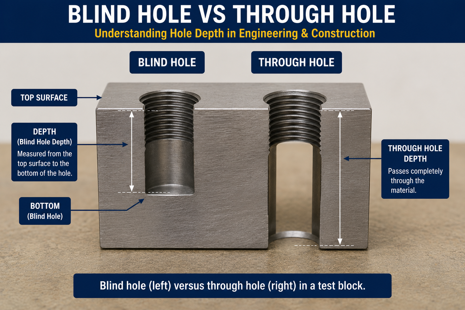
⭐ Tap Drill Size for Blind Holes
A blind hole must be drilled deeper than the desired thread length to accommodate the tap’s geometry.
Required thread depth
The actual usable thread length needed for the application, based on the fastener engagement requirement.
Tap chamfer allowance
Most taps have a chamfered lead of several threads at the tip that do not form a full thread profile, requiring additional hole depth beyond the usable thread length.
Drill point allowance
A standard twist drill leaves a conical point at the bottom of the hole rather than a flat bottom, requiring additional depth to reach full diameter at the desired thread depth.
Chip clearance space
Extra depth beyond the tap’s chamfer helps accommodate chips and debris at the bottom of a blind hole, reducing the risk of the tap bottoming out and breaking.
| Feature | Through Hole | Blind Hole |
|---|---|---|
| Chip evacuation | Easier, chips exit the far side | More difficult, chips accumulate at the bottom |
| Drill depth | Drilled completely through | Controlled to a specific depth with allowances |
| Tap style | Spiral point often preferred | Spiral flute often preferred for chip removal |
| Bottom clearance | Not applicable | Important to avoid tap breakage at the hole bottom |
A commonly used general approach adds roughly the tap’s chamfer length plus a small safety margin to the required thread depth when calculating total drill depth, though the exact addition depends on the specific tap’s chamfer style and length. Thread engagement length (how deep the thread must go) and thread engagement percentage (how much of the thread height is present) are two different considerations that should both be checked for the application.
Tapping Torque, Chip Evacuation & Tap Breakage
Drill size directly affects how much work the tap must do and how likely it is to fail during tapping.
Drill size and tapping torque
A smaller pilot hole means more material for the tap to remove or displace, increasing tapping torque; a larger pilot hole reduces torque but also reduces thread engagement and potential joint strength.
Common causes of tap breakage
Hole too small for the intended engagement, wrong tap type for the material, inadequate or wrong lubricant, poor alignment, excessive speed, poor chip evacuation in blind holes, incorrect tapping depth, and material work hardening.
Spiral point vs spiral flute taps
Spiral point taps push chips forward, commonly useful for through holes; spiral flute taps pull chips back and out, commonly useful for blind holes. Actual selection still depends on material and the tap manufacturer’s specific recommendation.
Lubrication
Cutting oil or tapping fluid appropriate to the material reduces friction and heat, extending tap life and improving thread finish; aluminum and stainless steel each benefit from material-specific lubricant selection.
⭐ Tap Drill Chart for Construction Fasteners
Tapping is a distinct process from other construction hole types.
Anchor bolts
Anchor installation holes are not automatically tap drill holes; cast-in anchor bolts, mechanical (wedge/sleeve) anchors, and adhesive anchors each have their own manufacturer-specified hole diameter that is unrelated to the tap drill formulas on this page. See the Anchor Bolt Size Chart.
Threaded rod
UNC, UNF and metric threaded rod each require correctly matched nuts; tap drill charts apply when creating a matching internal thread, not when using the rod with standard nuts.
Steel brackets and structural hardware
Tapped holes in steel brackets should follow the appropriate UNC, UNF or metric tap drill chart above, matched to the actual bolt grade being installed. See the Bolt Grade Chart.
Bolt torque is separate
Tap drill size determines the internal thread; correct tightening torque for the installed bolt is a separate consideration covered in the Bolt Torque Chart.
⭐ Tap Drill Visual Guide
Original diagrams explaining tap drill anatomy, thread engagement, and cutting vs forming taps.
How to Choose the Correct Tap Drill
Follow this sequence for a reliable tap drill selection.
Determine the exact thread designation required, such as 3/8-16 UNC or M10 x 1.5.
Confirm which system the thread belongs to before selecting a chart.
Match the exact series or pitch, not just the nominal diameter.
Confirm which tap type will be used, since they require different drill sizes.
Select an appropriate percentage based on material and application requirements.
Apply the appropriate formula for the tap type and thread system.
Round to the nearest available number, letter, fractional, or metric drill size.
Confirm the selection against the specific tap product’s documentation.
Account for required thread depth, tap chamfer, and chip clearance for blind holes.
Double-check diameter and depth calculations before committing to the final hole.
⭐ Tap Drill Identification Worked Examples
These examples show the calculation and selection process step by step.
1. 1/4-20 UNC
2. 1/2-13 UNC
3. M8 x 1.25
4. M12 x 1.75
5. 1/4-28 UNF Compared With 1/4-20 UNC
Common Tap Drill Mistakes
Most tapping failures trace back to one of these errors.
❌ Using tap diameter as drill size
The tap’s nominal size is always larger than the correct pilot hole.
❌ Using the wrong thread pitch
Confirm exact TPI or pitch before calculating; a wrong pitch produces a wrong drill size.
❌ Confusing UNC and UNF
Same diameter, different TPI, requiring different tap drills.
❌ Using a metric drill for an inch thread without checking
Verify the actual decimal diameter matches, not just an approximate label.
❌ Using cutting-tap dimensions for a forming tap
Forming taps require a larger pilot hole than cutting taps for the same thread.
❌ Assuming 75% engagement is mandatory
It is a common reference basis, not a universal requirement.
❌ Ignoring material
Material affects appropriate engagement percentage, tap type and lubrication.
❌ Ignoring hole depth
Blind holes need extra depth beyond the required thread length.
❌ Wrong drill size for a blind hole
Account for tap chamfer and chip clearance, not just thread length.
❌ Confusing tap drill with clearance drill
These serve opposite purposes and must not be interchanged.
❌ Skipping the commercial drill check
A calculated theoretical size still needs rounding to an available standard drill.
❌ Ignoring manufacturer’s tap recommendations
Specific tap products may specify different drill sizes than a general formula.
Frequently Asked Questions
📄 Download Tap Drill Chart PDF
Use the print button to create a print-ready or downloadable reference. Always verify against the tap manufacturer’s specific recommendation for critical or production work.
Cite or Embed This Chart
Copy the page-wide citation to reference the complete Tap Drill Chart.