Concrete Cover Chart 2026: Minimum Cover by Element, Exposure & Bar Size
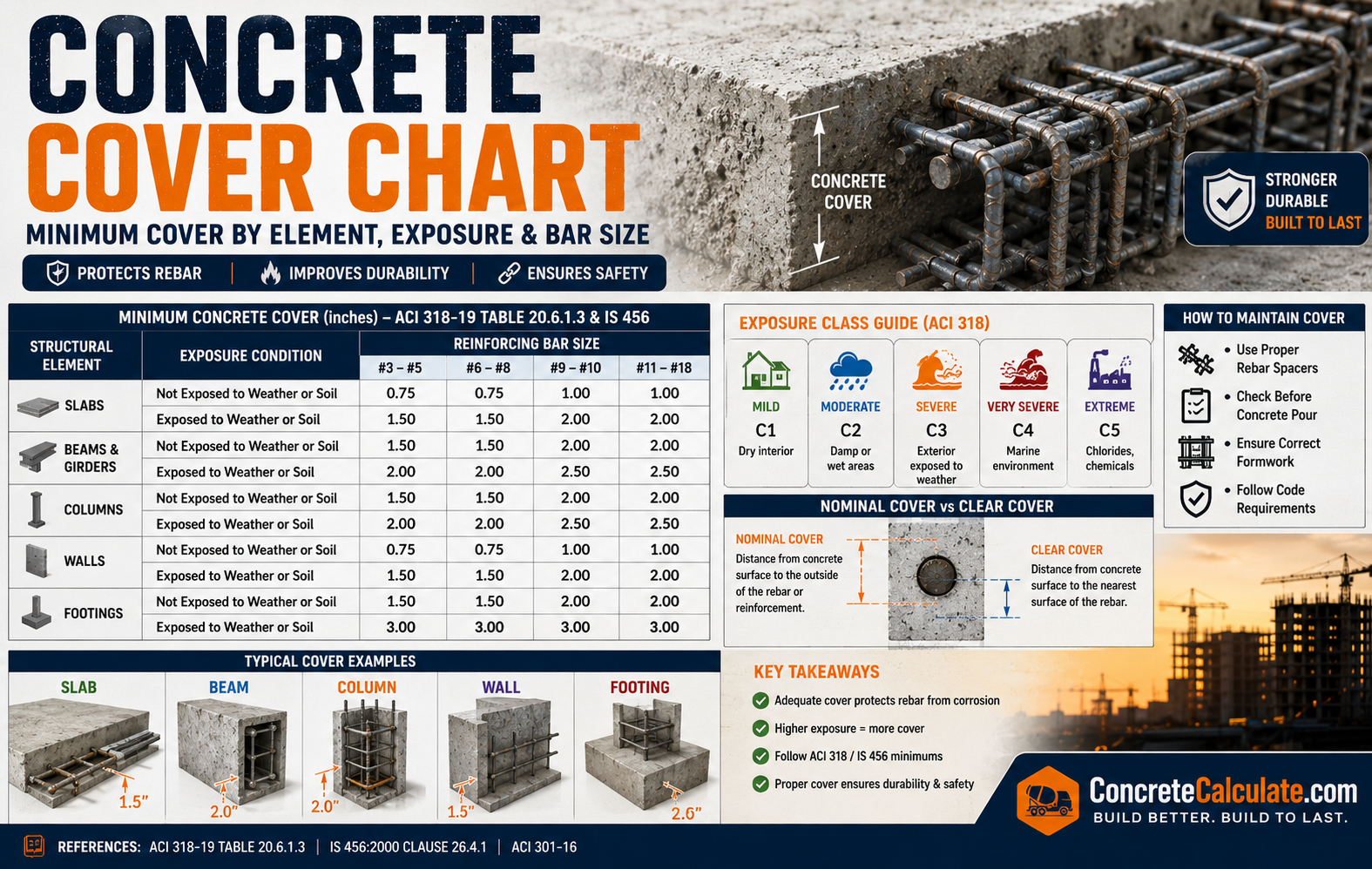
Concrete Cover Chart
Minimum Cover by Element, Exposure & Bar Size
The complete concrete cover reference for contractors, engineers, and inspectors — minimum cover by structural element, exposure condition, rebar size, and exposure class.
 Reviewed by Muhammad Ramzan Babar, PhD Researcher (Plasma Physics) & Calculator Developer — View Profile
⭐ Master Concrete Cover Chart
Complete reference for minimum concrete cover across common reinforced concrete members, per ACI 318 default conditions.
How to Read This Chart
Cover requirements depend on both the member type and exposure condition — always use the larger of the two governing values. Verify your rebar layout with our Rebar Cover Calculator.
| Member | Minimum Cover (in) | Minimum Cover (mm) |
|---|---|---|
| Slabs (interior) | 3/4″ | 19 mm |
| Beams (interior) | 1.5″ | 38 mm |
| Columns (interior) | 1.5″ | 38 mm |
| Walls (interior) | 3/4″–1.5″ | 19–38 mm |
| Footings (against earth) | 3″ | 75 mm |
| Foundations (exposed to weather) | 2″ | 50 mm |
| Staircases | 1″ | 25 mm |
| Retaining Walls (earth face) | 2″–3″ | 50–75 mm |
Source: ACI 318-19 Table 20.5.1.3.1. Always verify against project-specific structural drawings and local exposure requirements.
Concrete Cover Requirements by Structural Element
Cover requirements vary by member type since each carries different exposure and structural demands.
| Structural Element | Minimum Concrete Cover |
|---|---|
| Slabs | 3/4″ (19mm) interior; 1.5″–2″ (38–50mm) exposed |
| Beams | 1.5″ (38mm) interior; 2″ (50mm) exposed |
| Columns | 1.5″ (38mm) interior; 2″ (50mm) exposed |
| Walls | 3/4″–1.5″ (19–38mm) depending on bar size/exposure |
| Footings | 3″ (75mm) cast against earth |
| Foundations | 2″–3″ (50–75mm) depending on soil contact |
| Staircases | 1″ (25mm) typical |
| Retaining Walls | 2″–3″ (50–75mm) earth-facing side |
Concrete Cover Chart by Rebar Size
Per ACI 318, larger bars require more cover in weather/soil-exposed conditions since they carry higher corrosion risk exposure area.
| Rebar Size | Interior/Not Exposed | Exposed to Weather/Soil |
|---|---|---|
| #3 | 3/4″ | 1.5″ |
| #4 | 3/4″ | 1.5″ |
| #5 | 3/4″ | 1.5″ |
| #6 | 3/4″ | 2″ |
| #7 | 3/4″ | 2″ |
| #8 | 3/4″ | 2″ |
| #9 | 3/4″ | 2″ |
| #10 | 3/4″ | 2″ |
| #11 | 3/4″ | 2″ |
| #14 | 1.5″ | 2″ |
| #18 | 1.5″ | 2″ |
“Interior/Not Exposed” values apply to slabs, walls, joists per ACI 318 Table 20.5.1.3.1. Beams/columns use 1.5″ regardless of bar size when not exposed. Cross-reference with our Rebar Size Chart.
⭐ Concrete Cover by Exposure Condition
Exposure condition often governs cover requirements more than strength or bar size alone.
| Exposure Condition | Recommended Cover |
|---|---|
| Interior Dry Conditions | 3/4″–1.5″ (19–38mm) |
| Exterior Weather Exposure | 1.5″–2″ (38–50mm) |
| Soil Contact | 2″–3″ (50–75mm) |
| Marine Environments | 2″–3″ (50–75mm), often with corrosion-resistant rebar |
| Freeze-Thaw Regions | 1.5″–2″ (38–50mm), with air-entrained concrete |
| Chemical Exposure | 2″–3″ (50–75mm), depending on chemical severity |
Concrete Cover by Construction Application
Practical cover recommendations by common project type.
| Project | Recommended Cover |
|---|---|
| Driveways | 1.5″–2″ (38–50mm) |
| Sidewalks | 1.5″ (38mm) |
| Patios | 1.5″ (38mm) |
| Garage Floors | 1.5″–2″ (38–50mm) |
| Foundations | 2″–3″ (50–75mm) |
| Basement Walls | 1.5″–2″ (38–50mm) |
| Bridge Decks | 2″–2.5″ (50–65mm), often epoxy-coated bars |
| Parking Structures | 1.5″–2″ (38–50mm) |
Plan reinforcement layout with our Rebar Grid Calculator.
Concrete Cover for Slabs Chart
Ground-supported slabs and suspended slabs have different exposure profiles requiring different cover.
| Slab Type | Minimum Cover |
|---|---|
| Ground Slabs | 1.5″–2″ (38–50mm), on grade with vapor barrier |
| Suspended Slabs | 3/4″–1″ (19–25mm) top; 3/4″ (19mm) bottom, interior |
| Roof Slabs | 1″–1.5″ (25–38mm), weather-exposed |
| Industrial Floors | 1.5″–2″ (38–50mm), abrasion/chemical resistant |
Concrete Cover for Beams & Columns Chart
Primary structural members generally need more cover than secondary elements due to higher load demands and longer design life expectations.
| Member Type | Minimum Cover |
|---|---|
| Beams (interior) | 1.5″ (38mm) to stirrups |
| Columns (interior) | 1.5″ (38mm) to ties |
| Primary Structural Members | 1.5″–2″ (38–50mm) |
| Secondary Members | 3/4″–1.5″ (19–38mm) |
Design your member dimensions with our Concrete Beam Calculator or Concrete Column Calculator.
Concrete Cover for Footings & Foundations
Footings cast directly against soil require the most cover of any common member, since there’s no formwork barrier.
| Foundation Type | Minimum Cover |
|---|---|
| Spread Footings | 3″ (75mm) cast against earth |
| Strip Footings | 3″ (75mm) cast against earth |
| Mat Foundations | 3″ (75mm) bottom; 2″ (50mm) top if formed |
| Pile Caps | 3″ (75mm) bottom, in soil contact |
| Grade Beams | 2″–3″ (50–75mm), depending on soil contact |
Estimate footing volume and rebar layout with our Concrete Footing Calculator and Foundation Calculator.
Concrete Cover by Concrete Strength
Cover requirements are largely independent of strength — exposure condition usually governs, not PSI alone.
| Concrete Strength | Typical Cover Recommendation |
|---|---|
| 3,000 PSI | Follows exposure-based cover, not strength-based |
| 3,500 PSI | Follows exposure-based cover, not strength-based |
| 4,000 PSI | Follows exposure-based cover, not strength-based |
| 5,000 PSI | Follows exposure-based cover, not strength-based |
| 6,000 PSI | May allow reduced cover in some codes due to lower permeability |
Key Insight
ACI 318 and IS 456 cover tables are organized primarily by exposure condition and bar size — not compressive strength. A 6,000 PSI slab in soil contact still needs the same cover as a 4,000 PSI slab in the same exposure. Check strength independently on our Concrete PSI Strength Calculator.
Concrete Cover by Exposure Class
Design standards like IS 456 classify exposure severity into five standard classes.
| Exposure Class | Cover (mm) | Min Grade | Example Conditions |
|---|---|---|---|
| Mild | 20mm | M20 | Fully protected, dry interiors |
| Moderate | 30mm | M25 | Sheltered from severe rain, interior RCC |
| Severe | 45mm | M30 | Exposed to rain, alternate wet/dry, coastal (>500m) |
| Very Severe | 50mm | M35 | Coastal environment, aggressive soil/groundwater |
| Extreme | 75mm | M40 | Tidal zone, direct seawater splash, aggressive chemicals |
Source: IS 456:2000, Table 16. Always use the larger of durability-based and fire-resistance-based cover requirements.
⭐ Nominal Cover vs Clear Cover Chart
These terms are frequently confused on site — knowing the difference prevents under- or over-specifying reinforcement placement.
| Term | Definition | Measurement Method | Design Purpose | Typical Uses |
|---|---|---|---|---|
| Clear Cover | Actual distance from concrete surface to nearest bar surface | Direct measurement with ruler/cover meter | Verify as-built protection of reinforcement | Site inspection, QA/QC checks |
| Nominal Cover | Specified design value the drawings call out | Design specification, not field-measured directly | Set the target cover accounting for tolerance | Structural drawings, specifications |
| Effective Cover | Distance to centroid of main bar (clear cover + stirrup dia + half bar dia) | Calculated value | Used in flexural/moment capacity calculations | Structural design and analysis |
Concrete Cover Tolerance Chart
Construction tolerances account for practical placement variability without compromising minimum protection.
| Specified Cover | Allowable Tolerance |
|---|---|
| Less than 2″ (50mm) | ± 1/4″ (6mm) |
| 2″ to 3″ (50–75mm) | ± 3/8″ (10mm) |
| Greater than 3″ (75mm) | ± 1/2″ (12mm) |
Tolerances allow minor field variation but cover must never fall below the specified minimum — only above it, within the allowed range.
Concrete Cover Spacers Guide
Choosing the right spacer type ensures cover is maintained consistently during the pour.
| Spacer Type | Recommended Applications |
|---|---|
| Plastic Spacers | Slabs, walls, general use; cost-effective and widely available |
| Concrete Spacers | Footings, foundations, soil-contact members; matches surrounding concrete |
| Steel Chairs | Elevated slab reinforcement, top mat support in suspended slabs |
| Wheel Spacers | Vertical walls and columns, rolls along formwork during placement |
Common Concrete Cover Mistakes
Field errors that compromise reinforcement protection and structural performance.
Insufficient cover
Placing rebar too close to the surface accelerates corrosion from moisture and chloride penetration, drastically shortening service life.
Excessive cover
Too much cover increases crack width under load and moves the bar farther from where it’s structurally most effective.
Poor spacer placement
Spacers placed too far apart or of inconsistent height allow the rebar cage to sag or shift during the pour.
Rebar movement during pouring
Foot traffic or concrete flow pressure can push bars out of position if they aren’t properly tied and supported.
Honeycombing
Poor consolidation around closely-spaced reinforcement near the cover zone leaves voids that reduce effective cover and let in moisture.
Corrosion due to inadequate cover
The most costly long-term consequence — rusting steel expands, cracks, and spalls the surrounding concrete, requiring expensive repair.
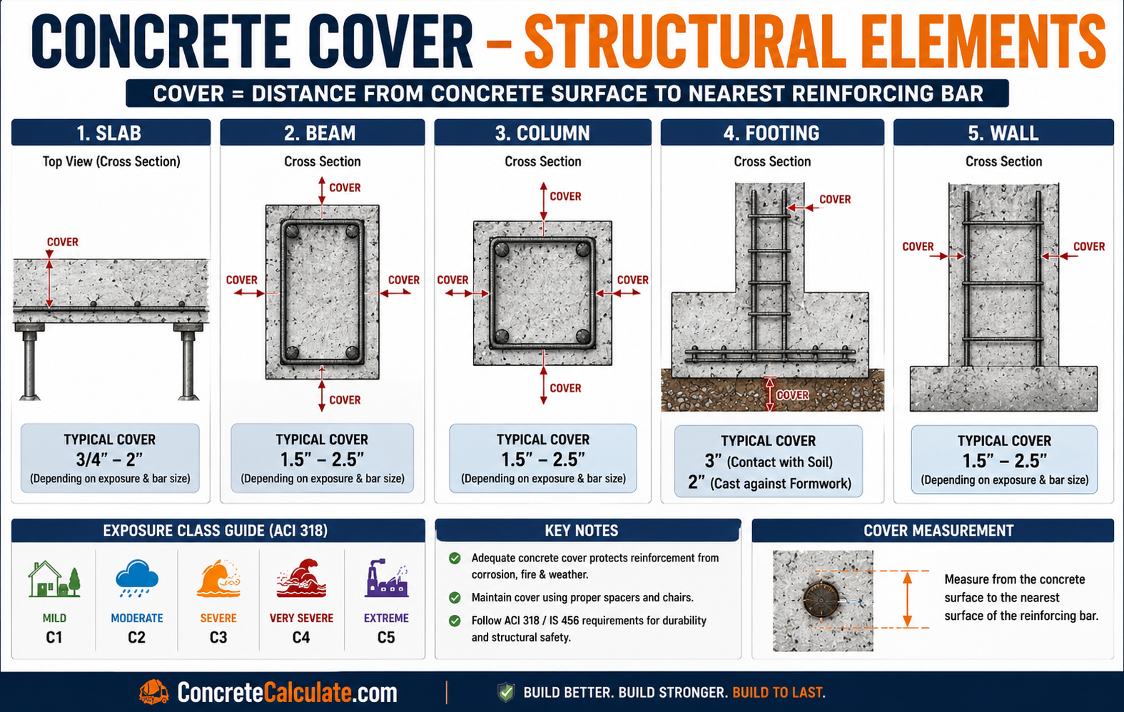
⭐ Visual Concrete Cover Guide
Cover distance illustrated by member type — one of the most valuable references for field crews and inspectors.
Slab Cover
3/4″–2″ from top/bottom surface to bar, depending on exposure
Beam Cover
1.5″–2″ from surface to stirrup, measured on all sides
Column Cover
1.5″–2″ from surface to tie, uniform around perimeter
Footing Cover
3″ from earth-facing surface to bottom reinforcement mat
Wall Cover
3/4″–1.5″ interior face; 2″+ on earth-retaining face
Contractor Worked Examples
Real-world cover decisions for common job scenarios.
Residential Foundation
Garage Floor Slab
Retaining Wall
Reinforced Beam
Structural Column
Frequently Asked Questions
📥 Download Concrete Cover Chart PDF
Use your browser’s print function to instantly save this page as a PDF. This avoids broken file links and gives you an always up-to-date printable field reference for engineers, contractors, inspectors, and students.