C Purlin Size Chart 2026 – Dimensions, Thickness, Weight & Span Reference
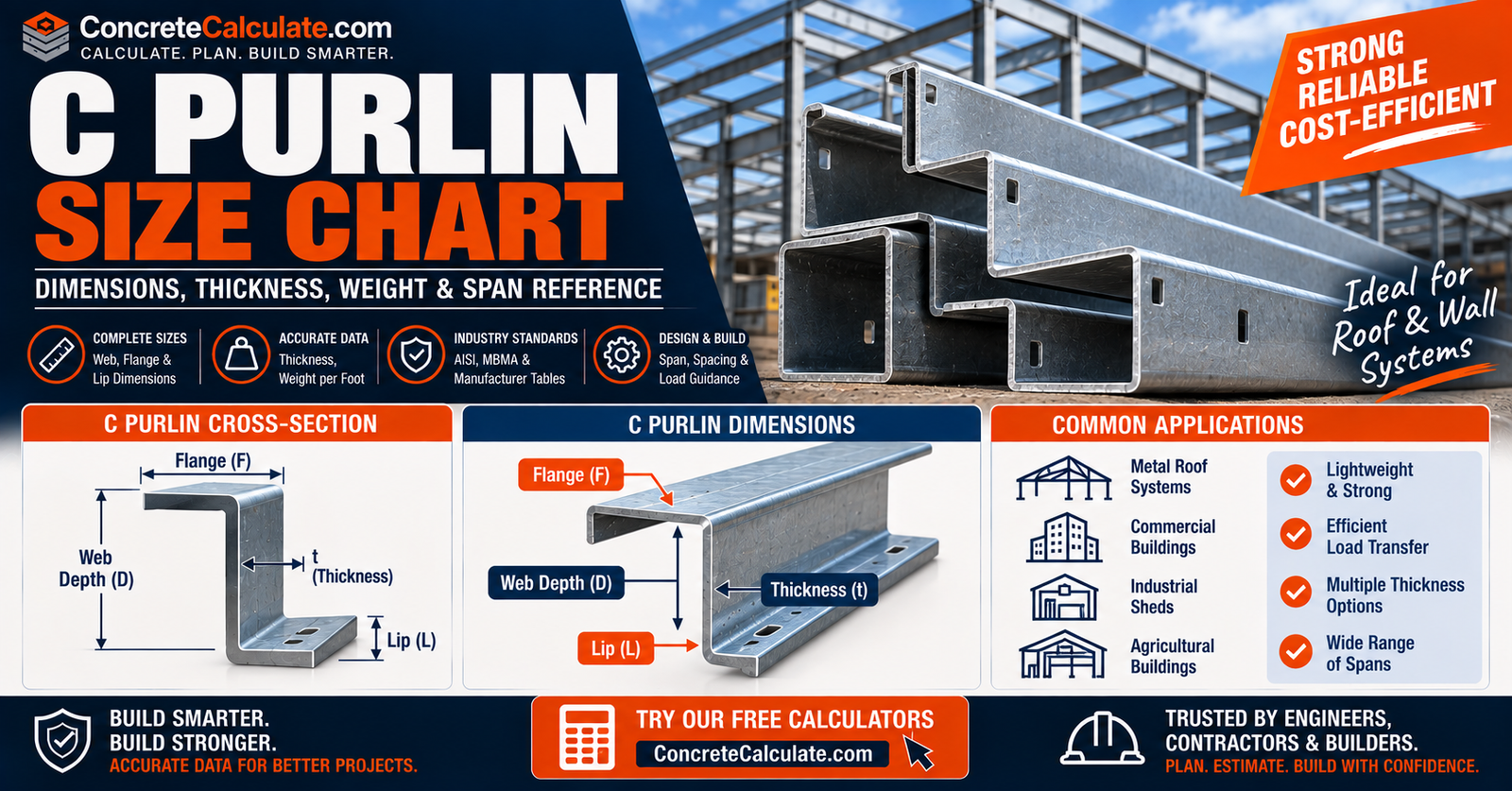
C Purlin Size Chart
Dimensions, Thickness, Weight & Span Reference
Actual web depth, flange width, lip, base steel thickness, and weight per foot for common Cee-purlin product lines, cross-checked against current manufacturer data, plus shear center behavior, span versus spacing, and AISI/MBMA load-table guidance for U.S. metal building framing.
 Reviewed by Muhammad Ramzan Babar, PhD Researcher (Plasma Physics) & Calculator Developer, View Profile
An “8-inch” C purlin is not a complete structural specification
Cold-formed C purlins have no single nationally standardized dimensional series comparable to AISC W-shapes. Current MBCI and Metal Sales catalogs show Cee sections at the same nominal depth differing in flange width, gauge, weight per foot, coating, and section properties. Identify the exact manufacturer and product line before ordering or designing with a C-purlin section.
C Purlin Size Chart, Quick Reference
Sizes below are grouped by manufacturer product line rather than mixed together, since actual flange width, thickness, and weight differ by brand even at the same nominal web depth.
Common C Purlin Sizes (MBCI Cee-Only Product Line)
| Nominal Size | Gauge | Base Thickness (in.) | Weight (lb/ft) | Weight (kg/m) |
|---|---|---|---|---|
| 6 x 3 | 16 | 0.0598 | 2.54 | 3.78 |
| 6 x 3 | 14 | 0.0747 | 3.04 | 4.52 |
| 6 x 3 1/2 | 16 | 0.0598 | 2.65 | 3.94 |
| 6 x 4 | 14 | 0.0747 | 3.31 | 4.93 |
| 8 x 4 | 14 | 0.0747 | 3.97 | 5.91 |
| 8 x 4 | 12 | 0.1046 | 5.93 | 8.82 |
| 10 x 4 | 14 | 0.0747 | 4.44 | 6.61 |
| 10 x 4 | 12 | 0.1046 | 6.63 | 9.87 |
| 11 x 3 | 14 | 0.0747 | 4.21 | 6.27 |
| 12 x 4 | 14 | 0.0747 | 4.91 | 7.31 |
| 12 x 4 | 12 | 0.1046 | 7.33 | 10.91 |
Values shown are drawn directly from MBCI’s published Cee-only product table. Metal Sales publishes a comparable but not identical range, with web heights of 4, 6, 8, 9, 10, and 12 in., flange widths of 2.5, 3, 3.5, and 4 in., and 12, 14, and 16 gauge product families.
C Purlin Thickness Quick Chart
| Gauge Label | Base Thickness (in.) | Base Thickness (mm) | Typical Availability |
|---|---|---|---|
| 16 gauge | 0.0598 | 1.52 | Lighter sections, smaller depths |
| 14 gauge | 0.0747 | 1.90 | Widely available across most depths |
| 13 gauge | 0.0897 | 2.28 | Select sizes, manufacturer-specific |
| 12 gauge | 0.1046 | 2.66 | Heavier sections across most depths |
Base steel thickness is the primary engineering value. Gauge is a secondary, market-facing label and should always be paired with the manufacturer’s actual published thickness.
C purlin size does not equal allowable span
An 8-in. or 10-in. C purlin does not have one universal allowable span. Capacity depends on the exact section, steel thickness and grade, purlin spacing, applied load, restraint, roof system, and deflection criteria.
What Is a C Purlin?
A cold-formed, thin-walled secondary structural member with a C-shaped cross-section.
A C purlin, or Cee purlin, is a cold-formed, thin-walled steel secondary framing member with one web, two flanges, usually edge lips or stiffeners, and an overall C-shaped cross-section. Manufacturer literature describes Cee purlins as secondary framing used in metal building systems that distribute loads from the roof or wall surfaces to the building’s primary framing, such as rigid frames, rafters, or trusses.
C Purlin vs Z Purlin
The right question is not which shape is stronger, but which section and system fit the span, loads, restraint, and framing configuration.
| Feature | C Purlin | Z Purlin |
|---|---|---|
| Shape | C | Z |
| Symmetry | Singly symmetric | Unsymmetric, oblique principal axes |
| Nesting for laps | Limited | Excellent with unequal flanges |
| Continuous lapped systems | Less natural | Very common |
| Simple-span use | Common | Common |
| Wall-girt use | Common | Common |
| Structural behavior | Cee-specific | Zee-specific |
This page owns Cee geometry and C-specific use cases. For unequal-flange nesting, lap length, and continuous lapped-line behavior, see the dedicated Z Purlin Size Chart.
C Purlin vs Hot-Rolled C-Channel
These terms are frequently confused online, but they describe different product categories designed under different rules.
| Property | Cold-Formed C Purlin | Hot-Rolled C-Channel |
|---|---|---|
| Manufacturing | Roll-formed from sheet or coil | Hot-rolled from billet |
| Wall type | Thin-walled, usually lipped | Thicker rolled section |
| Designation system | Manufacturer-specific gauge/size labels | AISC C or MC designation |
| Design provisions | AISI cold-formed steel provisions | AISC hot-rolled steel provisions |
| Typical use | Secondary framing in metal buildings | Primary or heavier structural framing |
The 2024 IBC directs cold-formed carbon and low-alloy steel structural members to AISI S100, which is a fundamentally different design specification from the hot-rolled AISC provisions used for C and MC channels. For hot-rolled channel dimensions and section properties, see the Steel Channel Size Chart.
How to Read a C Purlin Size Designation
Manufacturer naming can encode web depth, flange width, thickness, and product series, but not consistently across brands.
A designation such as 8 x 4 Cee typically means an approximately 8-in. web and a 4-in. flange, with thickness specified separately as a gauge or decimal value. There is no single national naming rule that guarantees every “8×4 Cee” from every manufacturer has identical lip, bend radius, thickness, steel strength, or section properties. MBCI’s current tables show multiple nominal Cee families, such as 6×3, 6×3 1/2, 6×4, 8×4, 10×4, 11×3, and 12×4, with different weights by gauge for sections that share a similar nominal depth label.
C Purlin Dimension Anatomy
Four geometric features define a C-purlin cross-section and drive its structural behavior.
| Dimension | What It Means |
|---|---|
| Web Depth (D) | Overall vertical dimension of the section, the primary nominal-size label |
| Flange Width (B) | Horizontal projection from the web on each side |
| Lip / Edge Stiffener | Short return at the flange edge that stabilizes the flange |
| Base Metal Thickness (t) | Thickness of the steel sheet before coating, used for structural calculations |
C Purlin Web Depth Chart
Web depth is only one part of the section specification. It does not by itself determine capacity.
| Web Height Class | Metal Sales Availability | MBCI Availability |
|---|---|---|
| 4 in. | Yes | Yes (Cee/Zee general line) |
| 6 in. | Yes | Yes |
| 8 in. | Yes | Yes |
| 9 in. | Yes | Not published in Cee-only line |
| 10 in. | Yes | Yes |
| 11 in. | Not published | Yes (11 x 3) |
| 12 in. | Yes | Yes |
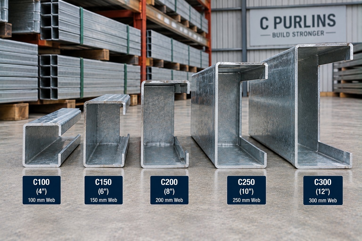
Metal Sales currently lists Cee web heights of 4, 6, 8, 9, 10, and 12 in. MBCI’s Cee-only table publishes a related but not identical set, including an 11-in. class not listed by Metal Sales.
C Purlin Flange Width Chart
Flange width affects section stiffness, local buckling behavior, roof-panel attachment, and connection geometry.
| Web Depth | Flange Width | Gauge Options | Weight (lb/ft) |
|---|---|---|---|
| 6 in. | 3 in. | 16, 14 | 2.54 to 3.04 |
| 6 in. | 4 in. | 14 | 3.31 |
| 8 in. | 4 in. | 14, 12 | 3.97 to 5.93 |
| 10 in. | 4 in. | 14, 12 | 4.44 to 6.63 |
| 11 in. | 3 in. | 14 | 4.21 |
| 12 in. | 4 in. | 14, 12 | 4.91 to 7.33 |
Metal Sales currently lists Cee flange widths from 2.5 to 4 in. across its product families. MBCI’s published Cee-only combinations show a related but manufacturer-specific range of flange and gauge pairings at each depth.
C Purlin Lip / Edge-Stiffener Dimensions
The lip is a structural feature, not a decorative detail.
The lip helps stiffen the flange edge, improves local stability, influences distortional buckling behavior, and factors directly into section-property calculations. Lip geometry should not be omitted from a professional Cee-section evaluation whenever the manufacturer publishes that dimension, since it materially affects the section’s effective properties under load.
C Purlin Thickness Chart
Base steel thickness should be the primary engineering value, with gauge treated as a secondary label.
| Gauge | Base Thickness (in.) | Thickness (mm) | Typical Cee Product Range |
|---|---|---|---|
| 16 ga | 0.0598 | 1.52 | Lighter sections at smaller depths |
| 14 ga | 0.0747 | 1.90 | Available across most published depths |
| 13 ga | 0.0897 | 2.28 | Select manufacturer/product families |
| 12 ga | 0.1046 | 2.66 | Heavier sections across most depths |
Current product examples commonly use 16, 14, and 12 gauge, with some manufacturer product families including 13 gauge as well. MBCI’s general Cee/Zee tables include 12, 13, 14, and 16 gauge, though specific Cee-only combinations vary by size.
Gauge vs Actual Base Steel Thickness
One of this page’s most important accuracy sections.
Gauge is a market and product label, while base thickness is the actual engineering dimension used in design calculations. Coated thickness equals base steel thickness plus the metallic coating, and different manufacturer conventions can create confusion if only a gauge number is shown without the corresponding base thickness in inches.
Editorial Rule
Always publish gauge and actual base steel thickness together. Never let a generic gauge chart replace the actual product specification published by the manufacturer.
C Purlin Weight per Foot Chart
Weight per linear foot is useful for estimating, shipping, and comparing sections, but it is a product-specific value.
| Cee Size | Gauge / Thickness | Weight (lb/ft) | Weight (kg/m) |
|---|---|---|---|
| 6 x 3 | 16 ga (0.0598 in.) | 2.54 | 3.78 |
| 6 x 3 | 14 ga (0.0747 in.) | 3.04 | 4.52 |
| 8 x 4 | 14 ga (0.0747 in.) | 3.97 | 5.91 |
| 8 x 4 | 12 ga (0.1046 in.) | 5.93 | 8.82 |
| 12 x 4 | 14 ga (0.0747 in.) | 4.91 | 7.31 |
| 12 x 4 | 12 ga (0.1046 in.) | 7.33 | 10.91 |
These are MBCI product values, not universal C-purlin weights. Metal Sales and other manufacturers publish their own weight tables for their specific Cee product lines, which may differ even at the same nominal depth and gauge label.
For general steel weight calculations beyond cold-formed sections, see the Structural Steel Weight Chart, or use the Steel Weight Calculator for custom takeoffs.
C Purlin Section Properties
A professional reference should go beyond a size and weight table.
A complete structural evaluation of a C-purlin section includes gross cross-sectional area, centroid location, moment of inertia about both axes, section modulus, radius of gyration, torsional constant, warping constant, and effective section properties where local buckling reduces the usable cross-section. Cold-formed thin-wall sections can lose effective width due to local buckling, so gross section properties alone do not determine allowable structural capacity, which is one major distinction from a basic steel-size table.
C Purlin Shear Center and Torsional Behavior
A strong technical differentiator between a serious engineering-oriented Cee reference and a basic supplier size list.
A conventional lipped Cee has symmetry about only one axis, and its shear center is offset from its centroid. Because loads are typically applied through the roof or wall panel rather than through the shear center, this offset can introduce torsion into a member that might otherwise be assumed to bend in simple, uniaxial fashion. This affects the purlin’s tendency to twist, its lateral stability, its behavior on sloped roofs, and the bracing requirements needed to control that twist. AISI’s cold-formed steel design provisions specifically define the distance from the shear center to the web midplane for C-sections and provide design criteria for singly symmetric members subject to combined bending and torsional loading, which reflects how significant this behavior is to a proper Cee design, not merely a theoretical detail.
Do not treat a C purlin as a simple solid rectangular beam. Its offset shear center means torsion, restraint, and bracing assumptions materially affect its real capacity under roof and wall loading.
What Determines the Required C Purlin Size?
A C purlin cannot be sized from nominal depth alone.
| Factor | Why It Matters |
|---|---|
| Span | Distance between primary supports along the purlin |
| Purlin Spacing | Sets the tributary roof or wall width carried by each purlin line |
| Web/Flange Geometry | Determines available section properties |
| Base Steel Thickness | Directly affects area, stiffness, and strength |
| Steel Yield Strength | Sets allowable stress limits used in design |
| Dead Load | Permanent roof, wall, and attached-system weight |
| Roof Live Load | Code-minimum maintenance/construction load |
| Snow and Drift | Can govern gravity design in many U.S. regions |
| Wind Uplift | Reversed loading condition with different restraint behavior |
| Roof Slope | Affects load resolution relative to the offset shear center |
| Simple vs Multi-Span Condition | Continuity changes internal moment and deflection behavior |
| Roof-Panel Restraint | Panel type and clip system affect lateral bracing |
| Bridging / Bracing | Provides discrete restraint and controls torsion/twist |
| Deflection Criteria | Serviceability limit separate from strength |
C Purlin Span vs Spacing
These are two separate variables that are frequently confused.
Span is the distance between primary supports along the purlin. Spacing is the distance between parallel purlins across the roof or wall. For uniform roof pressure q in psf and purlin spacing S in feet, the line load carried by the purlin is w = q multiplied by S, where w is expressed in pounds per linear foot.
C Purlin Spacing and Roof-Panel Span
Do not publish or rely on one universal spacing table.
| Roof Panel / System | Governing Limit on Spacing |
|---|---|
| Through-fastened panel systems | Panel’s own maximum allowable span rating |
| Standing-seam panel systems | Panel and clip system’s engineered span rating |
| Heavier gravity or snow load conditions | May reduce allowable panel span, tightening required spacing |
Spacing can be governed by roof-panel span, purlin capacity, snow, uplift, insulation or roof-system buildup, or architectural geometry. Manufacturer-specific systems may cite spacing values of several feet on center, but these are system values, not national rules. For general roof-panel span guidance, see the Metal Roof Panel Span Chart, and for a dedicated purlin-spacing walkthrough, see the Purlin Spacing Chart.
Why There Is No Universal C Purlin Span Chart
A depth-only span table is incomplete and can be unsafe if used without the full set of governing conditions.
A simple “Cee depth to maximum span” table is not sufficient
Maximum span depends on exact section geometry, base thickness, steel strength, spacing, gravity load, uplift, bracing and restraint, simple or continuous condition, and deflection criteria. A chart that lists only depth and a single span number necessarily omits most of these governing variables.
This page intentionally does not publish a universal C-depth-to-span table. Instead, the sections below explain how to correctly use a manufacturer’s engineered C-purlin load table for the exact section and project conditions involved.
How to Read a C Purlin Load Table
A practical, ordered workflow for using manufacturer load tables correctly.
Load Table Workflow
Single-Span vs Multi-Span C Purlins
Cees are particularly intuitive for simple-span applications, but they are not limited to simple spans.
A single-span C purlin runs as one section between two primary supports with reactions at each end, requiring no Z-style nesting. Simple-span behavior still depends on roof-panel restraint and lateral or torsional stability, so it should not be treated as inherently simpler from a design standpoint. Cees can also be used in multi-span systems depending on the manufacturer’s engineered system, though unlike Z purlins, Cees do not naturally nest into each other, so continuity details and splice or connection arrangements differ from a lapped Zee line.
C Purlin Splices and Connections
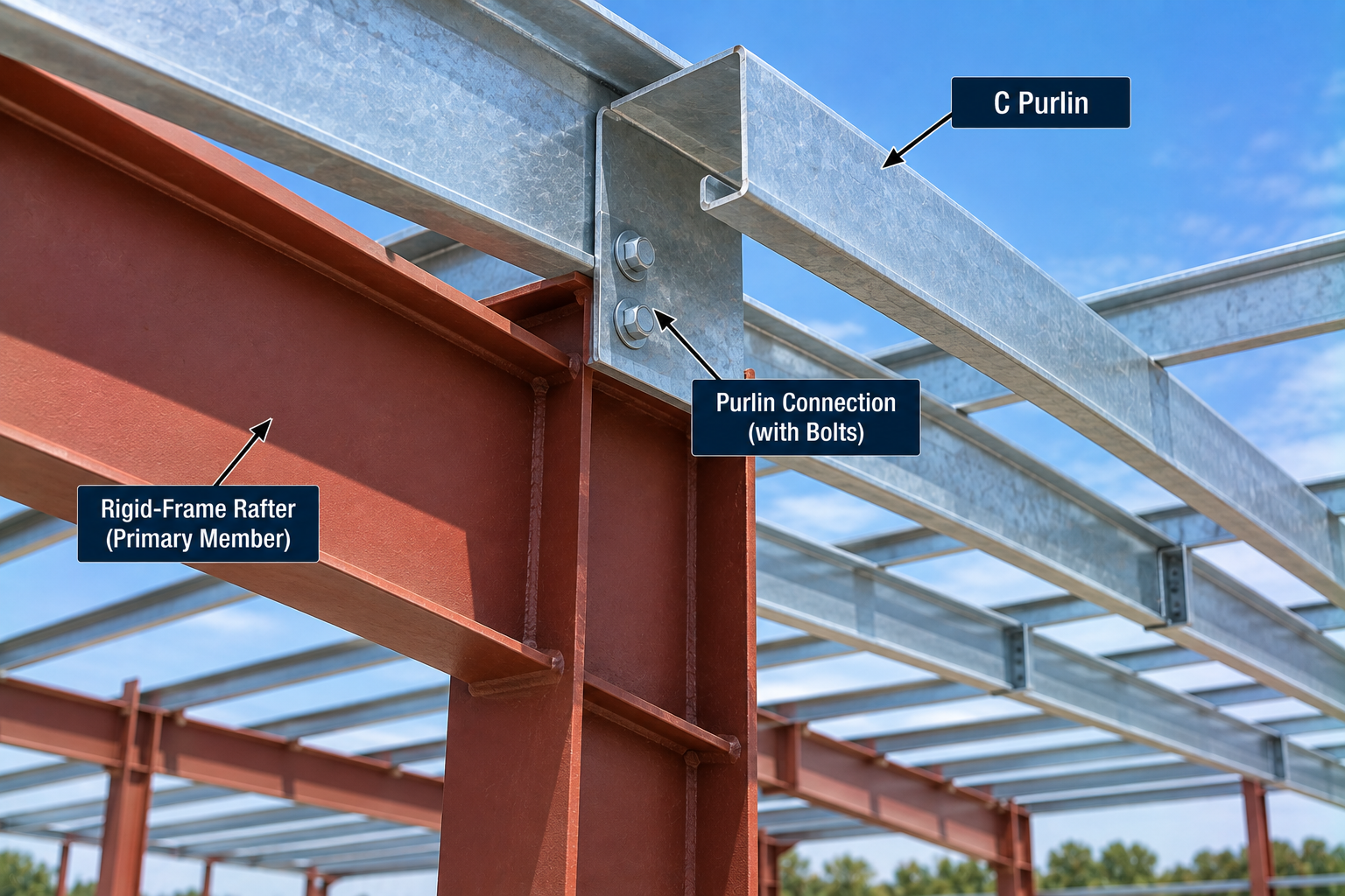
Connections must transfer reaction, uplift, and any applicable axial or bracing forces.
End connections for C purlins commonly use web bolts, splice plates, clips, cleats, or screws through punched holes in the section. The specific connection detail depends on the manufacturer’s engineered system and the forces that must be transferred at that location, so there is no single universal bolt pattern that applies to every Cee product or project.
Gravity Load Capacity of C Purlins
Downward loading combines several distinct load sources.
Gravity loading on a C purlin includes roof or wall sheeting self-weight, insulation, roof live load, snow, and any supported equipment where specifically designed for that purpose. Capacity should not be identified from section modulus alone, since local buckling, distortional buckling, and lateral-torsional behavior can govern before the gross section modulus limit is reached.
Wind-Uplift Capacity of C Purlins
Gravity capacity and uplift capacity are not necessarily the same value.
ASCE 7’s wind provisions govern roof wind pressures, including component and cladding considerations relevant to secondary framing. Under load reversal, the compression flange changes, roof-panel restraint can change, and torsional behavior can change relative to the gravity-load case. A C purlin that passes downward loading does not automatically pass wind uplift, and each condition should be checked independently against the manufacturer’s load table.
Snow, Drift, and Roof-Slope Effects
A C purlin that works in one location may not be appropriate in another with the identical span.
ASCE 7-22 includes specific snow provisions covering sloped roofs, partial loading, unbalanced snow, roof drifts, sliding snow, rain-on-snow, and ponding instability. These effects can significantly increase the required gravity capacity of a roof-framing system in snow-exposed regions.
Roof Slope and C Purlin Behavior
Roof slope can create load components relative to the C-section’s principal axes. Because the Cee’s shear center is offset from its centroid, slope and restraint conditions can contribute to twist, lateral movement, and combined bending beyond a simple vertical gravity case.
Roof Panel Restraint of C Purlins
C-purlin capacity should not be treated independently from roof-panel and bracing assumptions when the design method relies on that restraint.
Current national roof-framing design guidance for metal building systems specifically covers purlin design, continuous systems, diaphragm requirements, and system anchorage together, rather than treating the purlin as an isolated beam. This system-level view is directly relevant to Cees, since their offset shear center makes the actual restraint provided by roof panels and bridging especially important to real-world performance.
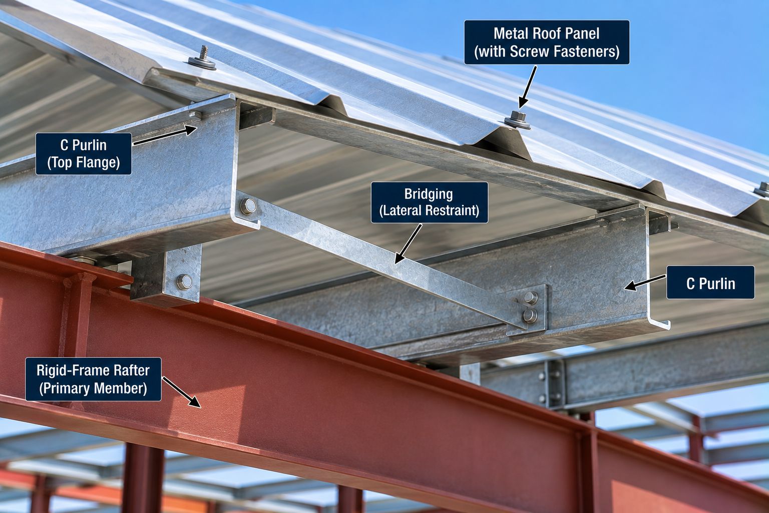
Through-Fastened vs Standing-Seam Roof Systems
A roof system can materially change how a Cee purlin behaves.
| Feature | Through-Fastened | Standing Seam |
|---|---|---|
| Panel connection | Direct fasteners | Clips |
| Thermal movement | More constrained | Accommodated by clip or slip system |
| Purlin restraint | Often more direct | System-dependent |
| Uplift behavior | Product-specific | Product-specific |
| Load tables interchangeable? | No assumption | No assumption |
Bridging, Anti-Roll, and Purlin Bracing
A thin-wall Cee can twist or buckle differently if its assumed bracing is absent.
Discrete bridging, anti-roll restraint, sag rods where used, flange braces, roof-panel restraint, and temporary erection bracing all contribute to a C purlin’s real-world stability. Final roof sheeting should not be assumed to provide erection-stage stability, since the panel system is often not fully attached until later in construction, leaving the purlin more dependent on discrete bracing in the interim.
C Purlin Deflection and Serviceability
Purlin selection must satisfy both strength and serviceability.
Possible governing controls include vertical deflection, roof-panel performance, roof drainage, ponding risk, ceiling or finish sensitivity, and appearance. This page does not state one universal deflection limit as mandatory, since the governing limit should come from the project specification, the manufacturer’s engineered system, or the applicable code requirement for the specific application.
C Purlin Materials, Grades, and Finishes
Steel yield strength, base thickness, coating, and corrosion protection are separate concepts, and capacity should never be inferred from finish color or coating alone.
Current manufacturer specifications identify Cee purlins as structural-quality steel with galvanized options. Metal Sales specifically identifies ASTM A653 structural-quality sheet with G90 coating for its Cee purlin product line, with minimum yield strength and tensile strength values stated in its published specification data. MBCI offers red-oxide and G90-galvanized finish options depending on the product. Not every C purlin nationwide is necessarily the same ASTM grade or coating, so the exact manufacturer and project specification should always govern.
C Purlin vs Girt and Eave Strut
Related secondary members with distinct locations and load paths.
| Member | Location |
|---|---|
| C Purlin | Secondary roof member |
| C Girt | Secondary wall member |
| Eave Strut | Roof-to-wall transition member, often a distinct shape or orientation |
A purlin and a girt may share a similar or identical Cee profile, but load direction, span, spacing, restraint, and connections can differ between the roof and wall applications. Metal Sales explicitly offers both Cee purlin and Cee wall girt product families as distinct offerings. An eave strut should not be treated as simply another C purlin unless the specific building system uses the same product for that purpose.
AISI, IBC, ASCE 7, and MBMA Design Requirements
The primary code and standards framework governing cold-formed C-purlin design in the United States.
The 2024 International Building Code states that cold-formed carbon and low-alloy structural members must be designed according to AISI S100. For the 2024 edition I-Codes, AISI identifies AISI S100-16 (2020) with Supplement 2-20 as the adopted North American Specification for cold-formed steel structural members. Cite the standard actually adopted by the governing code and jurisdiction, not merely the newest technical publication available, since a newer AISI S100-24 edition also exists but may not yet be the version legally adopted on a given project.
| Reference | Role in C Purlin Design |
|---|---|
| AISI S100 | North American cold-formed steel design specification, adopted by reference in the IBC |
| 2024 IBC | Building code that directs cold-formed member design to AISI S100 |
| ASCE 7-22 | National load framework covering dead, live, snow, rain, wind, seismic, and other loads and combinations |
| MBMA Roof Framing Design Guide | System-level guidance on purlin design, continuity, diaphragms, and anchorage, aligned with ASCE 7 and the current IBC |
For purlins specifically, the most relevant ASCE 7-22 provisions address roof and live loading, wind pressures including component and cladding effects, snow and drift, rain and ponding, and roof loads at solar panel installations. The Metal Building Manufacturers Association’s current Roof Framing Design Guide devotes complete coverage to purlin design methods, continuous purlin design, diaphragm requirements, and system anchorage, making it one of the main authority sources for a serious C-purlin reference.
C Purlins with Solar Panels and Added Roof Loads
Added rooftop systems can affect dead load, introduce concentrated attachment forces, change wind effects and load distribution, and affect roof-panel restraint. ASCE 7-22 specifically includes provisions addressing roof loads at solar panels. Added rooftop equipment should never be installed based only on a spare-looking purlin appearance; engineering verification of the purlin, panel, and connection capacity under the new loading is required.
Manufacturer C Purlin Tables and Availability
The single most important competitive insight for this page.
| Manufacturer | Web Heights | Flange Widths | Gauges | Finishes |
|---|---|---|---|---|
| Metal Sales | 4, 6, 8, 9, 10, 12 in. | 2.5, 3, 3.5, 4 in. | 12, 14, 16 | Red oxide, galvanized (ASTM A653 G90) |
| MBCI | 4 to 12 in. class, including 11 in. | Varies by nominal size (e.g., 3, 3 1/2, 4 in.) | 12, 13, 14, 16 (Cee/Zee general line) | Red oxide, G90 galvanized |
Current Metal Sales Cee offerings span web heights of 4, 6, 8, 9, 10, and 12 in., flange widths of 2.5, 3, 3.5, and 4 in., and 12, 14, and 16 gauge, in red-oxide or galvanized finish. MBCI’s current Cee-only offerings include combinations such as 6×3, 6×3 1/2, 6×4, 8×4, 10×4, 11×3, and 12×4, with weight varying by gauge within each nominal size. This proves that “8-inch C purlin” or “10-inch C purlin” is only a size class, not a complete structural specification, and the exact manufacturer and product line must be identified before design or ordering.
Common C Purlin Size Mistakes and Limitations
Selecting a C purlin from depth alone
Depth does not define flange width, lip, thickness, or weight.
Assuming every 8-in. Cee is identical
Flange width and gauge vary by manufacturer at the same nominal depth.
Ignoring the lip or edge stiffener
Lip geometry materially affects section properties and local buckling behavior.
Using gauge without actual base thickness
Always confirm the published base thickness in inches.
Mixing manufacturer dimensions and load tables
A load table only applies to the exact section it was developed for.
Confusing C purlin with hot-rolled C-channel
These are different product categories under different design provisions.
Confusing C purlin span with spacing
These are independent variables that both affect the required section.
Assuming a universal spacing distance
Spacing should come from panel span and load calculations, not a fixed rule.
Using a generic span chart with no load assumptions
Maximum span depends on many governing variables beyond depth.
Checking gravity but not uplift
Uplift is a separate structural check with different restraint behavior.
Ignoring snow drift and unbalanced snow
These effects can govern gravity design in many U.S. regions.
Assuming roof panels always provide full restraint
Restraint depends on the specific panel and clip system and construction stage.
Treating standing seam and through-fastened restraint identically
Each roof-panel system provides different lateral restraint assumptions.
Ignoring bridging and anti-roll requirements
These are part of the engineered structural system, not optional extras.
Using simple section modulus as full capacity
Local and distortional buckling checks are also required for cold-formed Cees.
Assuming all Cees are simple-span only
Cees can also be used in multi-span systems with appropriate splice or connection detailing.
Using Z-purlin lap assumptions for Cees
Cees do not nest into each other the way unequal-flange Zees do.
Read before finalizing a C-purlin selection
C-purlin dimensions are manufacturer-specific, and nominal depth is not a complete section specification. Gauge must always be paired with actual base steel thickness, and a Cee depth does not have one universal allowable span since span and spacing are separate variables. Steel strength, flange width, and lip dimensions all affect behavior, and gravity and uplift require separate checks. Snow, wind, rain, and added rooftop equipment may govern the design, and roof-panel restraint materially affects capacity, with standing-seam and through-fastened systems behaving differently. Bracing and bridging are part of the structural system, and manufacturer load tables apply only to their stated product and assumptions. Cees and hot-rolled C-channels are different structural systems entirely. Final design must comply with adopted AISI, IBC, and ASCE provisions along with project-specific engineering.
C Purlin Size FAQs
Download the C Purlin Size Chart
Get a printable reference including the size, thickness, weight, and section-property tables on this page for jobsite or office use.