How Thick Should a Concrete Driveway Be? 2026 Guide
Pour a driveway too thin and it cracks under normal vehicle weight within a few years. Pour it too thick and you’ve wasted money on every cubic yard. For most residential driveways, the answer is 4 inches minimum – but that’s only the starting point. This guide covers the exact thickness you need based on your vehicles, soil conditions, climate, and local code requirements – plus when rebar is required and how thickness affects your total cost.
The Standard Concrete Driveway Thickness
The industry standard for residential concrete driveways in the United States is 4 inches. This is the minimum thickness recognized by most local building codes and is sufficient for passenger cars and light SUVs on a properly compacted gravel base.
Most experienced concrete contractors recommend stepping up to 5 inches for the majority of homeowners. The extra inch doesn’t look any different but adds significant load-bearing capacity and resistance to cracking over time. The cost difference on a typical two-car driveway is modest – usually $200-400 total for an upgrade that extends the driveway’s life by years.
For context: a standard residential driveway sees vehicles weighing 3,000 to 6,000 pounds daily. A 4-inch slab handles that load fine. But the moment you add a pickup truck, camper, or delivery vehicle – anything over 8,000-10,000 pounds – a 4-inch slab is working at or near its design limit.
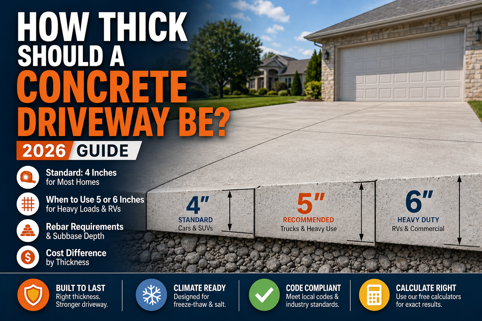
4 inches = minimum for residential driveways (passenger cars and light SUVs on stable, compacted soil). 5 inches = recommended for most homes. 6 inches = required for heavy trucks, RVs, and commercial traffic. Use our concrete driveway calculator to estimate materials for any thickness and driveway size.
Thickness by Vehicle Type and Use
The single biggest factor in determining driveway thickness is what will be driving on it. A driveway that routinely carries a 12,000-pound RV needs fundamentally different specifications than one that only sees a family sedan.
Passenger Cars and Light SUVs
Standard passenger vehicles weigh between 3,000 and 5,500 pounds. A 4-inch concrete slab on a compacted gravel subbase handles this load without issue. This is the bare minimum most codes allow and the most common residential specification across the country.
If your driveway is shorter than 20 feet and your soil is stable, 4 inches is a legitimate choice. If the driveway is long, sloped, or the soil has any soft spots, go to 5 inches for peace of mind.
Pickup Trucks and Full-Size SUVs
Full-size pickup trucks – F-150, Silverado, Ram 1500 – typically weigh 4,500 to 6,000 pounds empty. Loaded with a payload or towing equipment, that climbs to 8,000-10,000 pounds on the axles. If these vehicles are on your driveway daily, plan for 5 inches.
The extra inch increases the slab’s load-bearing capacity by roughly 50% compared to 4 inches. That margin matters when you’re parking heavy vehicles in the same spot every day, which creates repeated point loads that wear on a thinner slab over time.
RVs, Heavy Trucks, and Commercial Vehicles
Class A and Class C motorhomes weigh 15,000 to 35,000 pounds. Delivery trucks, concrete mixers, and commercial vehicles often exceed 26,000 pounds. For any of these, minimum thickness is 5 to 6 inches with rebar reinforcement required.
An RV parking pad or the driveway section where an RV regularly parks should be treated as a separate specification – at least 6 inches of concrete, 4000 PSI, with #4 rebar on 18-inch centers. Don’t spec this section the same as the rest of the driveway.
| Vehicle Type | Typical Weight | Min Thickness | Recommended | Reinforcement |
|---|---|---|---|---|
| Passenger cars / small SUVs | 3,000-5,000 lbs | 4 inches | 4-5 inches | Wire mesh |
| Full-size SUVs / light trucks | 5,000-8,000 lbs | 4 inches | 5 inches | #3 rebar recommended |
| Heavy pickups (loaded) | 8,000-12,000 lbs | 5 inches | 5-6 inches | #3 or #4 rebar |
| RVs and motorhomes | 12,000-35,000 lbs | 5 inches | 6 inches | #4 rebar required |
| Commercial vehicles | 20,000+ lbs | 6 inches | 6-8 inches | #4 rebar required |
📐 Calculate Your Driveway Concrete
Enter your driveway dimensions and thickness to get exact cubic yards, bags, and cost estimates in seconds.
Use Driveway Calculator →Soil Conditions and Subbase Requirements
Concrete thickness alone doesn’t determine driveway performance. What’s underneath matters just as much. A perfectly specified 5-inch slab will crack and sink if it’s sitting on poorly compacted or unstable soil.
The Gravel Subbase
Before any concrete goes down, you need a compacted gravel subbase. The standard depth is 4 to 6 inches of compacted crushed stone or gravel. In areas with clay soil, soft ground, or poor drainage, extend that base to 8 inches.
The subbase spreads vehicle loads over a wider area, provides drainage beneath the slab, and prevents frost heave from pushing the slab unevenly. Skip the proper base and your concrete – regardless of thickness – will settle unevenly and crack prematurely.
Soil Types and What They Mean for Thickness
Not all soil supports concrete equally. Here’s how your soil type affects the thickness decision:
- Sandy or gravelly soil: Naturally drains well and compacts firmly. A 4-inch slab on a 4-inch base is acceptable for standard residential use.
- Clay soil: Expands when wet and shrinks when dry, causing seasonal movement. Go to 5 inches minimum and use a 6-inch compacted gravel base.
- Fill soil or disturbed ground: Always soft and prone to settling. Requires thorough compaction testing before pouring. Use 5 to 6 inches minimum.
- Organic soil or topsoil: Remove it entirely before pouring. Never pour concrete over organic material – it compresses and decomposes, causing the slab to sink.
A 6-inch driveway on uncompacted fill will fail faster than a 4-inch driveway on a properly compacted base. Have the subbase tested with a plate compactor and verify at least 95% proctor density before scheduling the concrete pour. This step is not optional.
Drainage and Slope
Concrete driveways should slope a minimum of 1/8 inch per foot away from the house and toward the street or designated drainage area. Poor drainage causes water to pool, which accelerates surface deterioration, increases freeze-thaw damage, and can undermine the subbase over time.
If your driveway is in a low-lying area, consider adding a drainage channel (trench drain) at the base or alongside the driveway to redirect water away from the slab. Proper drainage extends driveway life as much as any thickness upgrade.
Rebar and Reinforcement by Thickness
Concrete is strong in compression but weak in tension. Reinforcement – either wire mesh or rebar – adds tensile strength to resist cracking when the ground shifts, temperature changes, or heavy loads flex the slab.
Wire Mesh for 4-Inch Slabs
Welded wire mesh (6×6-W2.9xW2.9 is standard) is the most common reinforcement for 4-inch residential driveways. It adds crack control without the cost and labor of rebar. Wire mesh must be placed near the middle of the slab – not on the ground where it contributes nothing.
Many contractors use fiber reinforcement (polypropylene fibers mixed into the concrete) in addition to or instead of wire mesh. Fiber doesn’t replace rebar for structural loads, but it significantly reduces plastic shrinkage cracks that form in the first 24 hours after placing.
Rebar for 5-Inch and Thicker Slabs
For slabs 5 inches or thicker – or any slab carrying heavy loads – rebar provides superior reinforcement. The standard specification for residential driveways is #3 rebar (3/8-inch diameter) on an 18-to-24-inch grid. For heavy trucks and RVs, use #4 rebar (1/2-inch diameter) on an 18-inch grid.
Rebar must be placed in the middle third of the slab thickness – typically 2 to 2.5 inches from the bottom for a 5-inch slab. It must have at least 1.5 inches of concrete cover from any edge or surface. Use chairs or supports to hold rebar at the correct height before the pour. Rebar lying on the subbase grade does nothing.
For a 4-inch driveway carrying only passenger vehicles on stable soil in a mild climate, fiber-reinforced concrete with wire mesh is solid. Once you go to 5 inches, add heavy vehicles, clay soil, or live in a freeze-thaw state, rebar is the right call. The cost of #3 rebar on a standard two-car driveway is roughly $150-250 in materials – a minimal investment for meaningful crack protection over 30 years.
| Slab Thickness | Recommended Reinforcement | Rebar Size | Spacing | Extra Cost (per sq ft) |
|---|---|---|---|---|
| 4 inches | Wire mesh or fibers | N/A | 6×6 mesh | $0.15-0.25 |
| 5 inches | #3 rebar grid | 3/8 inch | 18-24 inches o.c. | $1.00-1.50 |
| 6 inches | #4 rebar grid | 1/2 inch | 18 inches o.c. | $1.50-2.00 |
| 6+ inches (commercial) | #4 or #5 rebar | 1/2-5/8 inch | 12-18 inches o.c. | $2.00-3.00+ |
PSI and Thickness: How They Work Together
Thickness and concrete PSI (compressive strength) are two separate variables – but they work together to determine how well your driveway holds up. You can’t compensate for inadequate thickness by ordering higher PSI concrete, and you can’t skip upgrading PSI just because you went thicker.
The Right PSI for Driveways
For residential driveways in states with freezing winters – anywhere in the northern US – the minimum PSI per ACI 318 is 4000 PSI. This accounts for freeze-thaw exposure and deicing salt damage. In mild climates with no frost, 3000-3500 PSI is acceptable for light vehicles.
The cost difference between 3000 PSI and 4000 PSI ready-mix is about $15-20 per cubic yard in 2026. On a 600 sq ft, 5-inch driveway using roughly 9 cubic yards, that’s $135-180 more for significantly better durability. It’s almost always worth it.
How Thickness Affects Load Capacity
Increasing thickness has a non-linear effect on load capacity. Going from 4 inches to 5 inches doesn’t just add 25% more strength – the relationship is closer to increasing capacity by 50-95% because thicker slabs distribute loads over a larger area of the subbase. This is why one extra inch matters more than most homeowners expect.
Quick Reference: Thickness + PSI Combinations
Cold climate, passenger cars: 4 inches + 4000 PSI
All climates, light trucks: 5 inches + 4000 PSI
RVs / heavy loads: 6 inches + 4000 PSI + rebar
For a deep dive on PSI selection for every application, see our concrete PSI guide. It covers every strength grade, code references, and cost breakdowns for 2026.
Control Joints and Curing for Any Thickness
Getting the thickness right is only part of the job. Two things that are independent of thickness – control joints and curing – determine whether your driveway stays crack-free for decades or starts cracking in year two.
Control Joint Spacing
Concrete shrinks as it cures and expands and contracts with temperature changes year-round. Control joints give the concrete a planned place to crack – out of sight, in a straight line – instead of cracking randomly across the surface. The standard rule is to space joints at 2 to 3 times the slab thickness in feet.
- 4-inch slab: joints every 8-12 feet
- 5-inch slab: joints every 10-15 feet
- 6-inch slab: joints every 12-18 feet
Joints must be cut to a depth of at least one-quarter of the slab thickness – so 1 inch deep for a 4-inch slab. They should be cut within 12-24 hours of finishing while the concrete is still green, or formed with groover tools during finishing.
Curing Requirements
Concrete gains strength through hydration – a chemical reaction that requires moisture. If a freshly poured slab dries out too fast, hydration stops and the concrete never reaches its design PSI. Proper curing keeps the slab moist and at the right temperature for at least 7 days after placement.
In hot, dry, or windy weather, apply curing compound immediately after finishing, or cover the slab with wet burlap and plastic sheeting. In cold weather (below 40°F), protect the concrete from freezing for at least 3 days and ideally 7. For more on timing and curing methods, check our guide on concrete curing and drying time.
Wait at least 7 days before driving passenger vehicles on a new concrete driveway. Wait a full 28 days before parking heavy trucks, RVs, or trailers. The concrete looks hard after 24-48 hours but is only at 40-50% of its design strength. Driving on it too early causes permanent surface damage. See our full guide on when you can walk and drive on new concrete.
Cost Difference by Thickness
Adding thickness costs more concrete, which is the single largest expense in a driveway project. Here’s how thickness affects material cost and total installed cost on a standard 600 sq ft two-car driveway in 2026.
Concrete Volume by Thickness
Use this formula to calculate cubic yards needed: Length (ft) x Width (ft) x Thickness (in) / 12 / 27. For a 600 sq ft driveway:
- 4 inches: 7.4 cubic yards
- 5 inches: 9.3 cubic yards
- 6 inches: 11.1 cubic yards
| Thickness | Concrete (600 sq ft) | Material Cost (4000 PSI) | Installed Cost (Labor + Materials) | Lifespan (Cold Climate) |
|---|---|---|---|---|
| 4 inches | 7.4 cu yd | $1,295-$1,443 | $3,500-$5,000 | 20-30 years |
| 5 inches | 9.3 cu yd | $1,628-$1,814 | $4,200-$6,000 | 30-40 years |
| 6 inches | 11.1 cu yd | $1,943-$2,165 | $5,000-$7,500 | 40-50+ years |
The material cost difference between 4 and 5 inches is roughly $330-400 on a typical driveway. The difference between 4 and 6 inches is about $650-700. Compared to the cost of tearing out and replacing a failed driveway ($6,000-$15,000), paying for extra thickness upfront is sound math.
💼 Example: Planning a Driveway in Minneapolis, MN
Driveway size: 20 ft wide x 40 ft long = 800 sq ft
Vehicles: Two passenger cars + one F-250 pickup truck
Climate: Severe freeze-thaw, deicing salt use every winter
Soil: Clay-heavy, expansive
Specified thickness: 5 inches (F-250 requires extra capacity, clay soil + freeze-thaw warrants upgrade)
Subbase: 6 inches compacted crushed stone
Concrete: 4000 PSI, air-entrained (5-7% air), #3 rebar at 18 inches on center
Control joints: Every 12-13 feet (2.5x slab thickness)
Total concrete needed: 12.3 cubic yards
Estimated material cost: $2,150-$2,400 at $175-195 per cubic yard
Estimated installed cost: $6,500-$9,000 including subbase, forming, rebar, finishing, and sealing
🧮 Get Your Exact Concrete Volume and Cost
Enter your driveway dimensions and thickness. Our calculator returns exact cubic yards, bags, and current cost estimates for your area.
Use Slab Calculator →Local Code Requirements
While industry standards give you a starting point, your local building code has the final say on minimum driveway thickness. Most municipalities follow the national standard of 4 inches minimum for residential driveways, but requirements vary.
What Codes Typically Require
Most residential building codes in the US require:
- Minimum 4 inches of concrete for the main driveway surface
- Minimum 5 to 6 inches for the driveway apron (the section connecting to the street)
- Properly compacted subbase (typically 4-6 inches of gravel)
- Control joints at specified intervals
- Minimum 1/8-inch-per-foot slope away from the house
The apron requirement is particularly important. Many cities and counties require the first few feet of driveway adjacent to the street to be thicker than the rest – often 5 or 6 inches – because that section takes extra stress from vehicles making the transition from the road surface.
Permit Requirements
Many jurisdictions require a permit before replacing or installing a concrete driveway. Unpermitted work can create problems during a home sale or insurance claim. Contact your city or county building department before starting any driveway project. Permit costs typically run $50-200 for a residential driveway in 2026.
Some cities – particularly those with colder climates or heavy truck traffic – have updated their residential driveway codes to require 5 inches minimum. Don’t assume the national standard applies to your municipality. A quick call to your local building department before the project saves costly rework. Ask specifically about the apron thickness requirement near the street.
Common Thickness Mistakes to Avoid
These are the errors that cause driveways to fail well before their time – and every one of them is preventable.
1. Pouring 4 Inches on Clay Soil in a Freeze-Thaw Climate
This combination is behind the majority of premature driveway failures in the northern US. Clay soil expands and contracts seasonally. Freeze-thaw cycles stress the slab from above. Four inches doesn’t provide enough stiffness to resist both forces simultaneously. The result is a network of cracks within 5-10 years.
The fix is 5 inches minimum, a 6-inch compacted gravel base, and 4000 PSI air-entrained concrete. This combination adds $500-800 to the project cost and can double the driveway’s effective lifespan.
2. Using Thin Concrete at the Apron
Many contractors pour the entire driveway at the same uniform thickness – including the apron. The apron takes harder hits from vehicle undercarriages, snowplows, and the transition from street to driveway grade. Spec the apron at 5-6 inches even if the main driveway is 4 inches.
3. Skipping the Subbase or Under-Compacting It
A 6-inch driveway on poorly compacted fill will fail faster than a 4-inch slab on a proper base. The subbase is what everything sits on. Skipping proper subbase preparation is the most common and most damaging shortcut in driveway construction. Always require a compacted aggregate base with verified density before the pour.
4. Not Adding Extra Thickness at Soft Spots
If the subgrade has low spots, soft areas, or tree roots nearby, increase the slab thickness in those zones rather than filling with extra gravel and hoping. A 6-inch section over a problem area costs almost nothing extra in concrete but prevents a serious failure point.
5. Ordering 3000 PSI to Save Money on a Northern Driveway
This goes hand-in-hand with thickness but deserves its own mention. In states with hard winters, 3000 PSI concrete scales and spalls at the surface within 3-5 years of deicing salt exposure. The upgrade to 4000 PSI air-entrained concrete costs $15-20 per cubic yard extra – about $150-185 total on a typical driveway. Resurfacing that driveway later costs $3,000-8,000. This is not a savings.
6. Driving on It Too Early
Concrete at 5 days feels rock solid. It’s not. It’s at roughly 50-60% of design strength. Driving on a fresh driveway before 7 days causes surface impressions, edge cracking, and permanent strength reduction in the loaded zones. Wait the full 7 days for passenger vehicles and 28 days for heavy loads. It’s one of the easiest things to get right – and one of the most frequently ignored.
🎯 Key Takeaways: Concrete Driveway Thickness
- 4 inches is the minimum for residential driveways with passenger cars and light SUVs on stable, compacted soil
- 5 inches is the smart upgrade for most homeowners – especially with heavy vehicles, clay soil, or freeze-thaw climates
- 6 inches is required for RVs, heavy trucks, and commercial vehicles
- The subbase matters as much as the slab – always use 4-6 inches of compacted crushed stone, and 6-8 inches on poor soil
- Wire mesh is standard for 4-inch slabs; use #3 rebar for 5-inch slabs and #4 rebar for 6-inch or heavy-load applications
- Use 4000 PSI air-entrained concrete for any driveway exposed to freezing temperatures or deicing salts
- The cost difference between 4 and 5 inches on a 600 sq ft driveway is approximately $330-400 in materials – a fraction of replacement cost
- Control joints at 2-3x the slab depth in feet prevent random cracking – 8-12 feet apart for a 4-inch slab
- Cure the concrete for at least 7 days with moisture before exposing to traffic
- Wait 7 days for passenger cars and 28 days for heavy vehicles before using a newly poured driveway
- Check your local building code – apron thickness near the street is often required to be 5-6 inches
- Never pour over organic soil or topsoil – remove it entirely and replace with compacted aggregate
Frequently Asked Questions
🔧 Plan Your Driveway Project
Use our free concrete calculators to get exact materials, costs, and specifications for your driveway – any thickness, any size.
Explore All Calculators →