ASTM A490 Bolt Size Chart 2026: Dimensions, Holes & Strength
ASTM A490 Bolt Size Chart: Dimensions, Holes & Strength
Heavy-hex head sizes, UNC threads, thread length, bolt hole sizes, length selection, Group 150 pretension and coating restrictions for ASTM F3125 Grade A490 structural bolts.
 Reviewed by Muhammad Ramzan Babar, PhD Researcher (Plasma Physics) & Calculator Developer. View Profile
Key Facts
- ASTM A490 is now ASTM F3125 Grade A490, a 150 ksi class heavy-hex structural bolt furnished from 1/2 to 1-1/2 in.
- A 3/4 in. A490 bolt has a 1-1/4 in. head across flats, 3/4-10 UNC threads and a 1-3/8 in. standard thread length. The geometry matches A325, but the grades are not interchangeable.
- Standard hole for a 3/4 in. bolt is 13/16 in. Minimum pretension is 35 kips (tension, not torque).
- Coatings are restricted because of hydrogen embrittlement. Compare grades in the A325 Bolt Size Chart and Bolt Grade Chart.
A490 Bolt Size Chart: Quick Reference
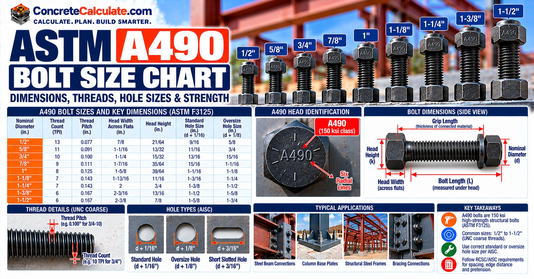
Heavy-hex dimensions, UNC threads and thread length for all nine standard sizes.
How to Read This Chart
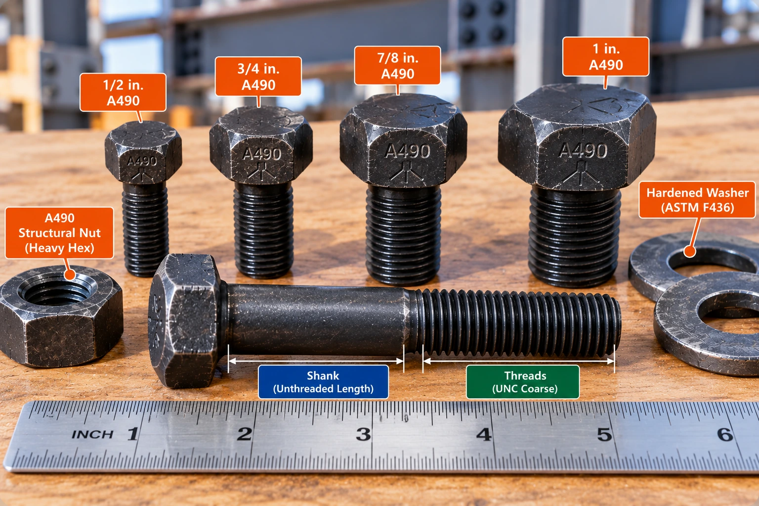
Read across a row from nominal diameter to the standard UNC thread, the heavy-hex head width across flats (the wrench or socket size), the basic head height and the nominal structural thread length. A 3/4 in. A490 bolt has a 1-1/4 in. head because heavy-hex structural heads are wider than ordinary hex heads. Head width is a wrench dimension, not the bolt size.
| Nominal diameter | UNC thread | Head across flats | Basic head height | Nominal thread length |
|---|---|---|---|---|
| 1/2 in. | 1/2-13 UNC | 7/8 in. | 5/16 in. | 1 in. |
| 5/8 in. | 5/8-11 UNC | 1-1/16 in. | 25/64 in. | 1-1/4 in. |
| 3/4 in. | 3/4-10 UNC | 1-1/4 in. | 15/32 in. | 1-3/8 in. |
| 7/8 in. | 7/8-9 UNC | 1-7/16 in. | 35/64 in. | 1-1/2 in. |
| 1 in. | 1-8 UNC | 1-5/8 in. | 39/64 in. | 1-3/4 in. |
| 1-1/8 in. | 1-1/8-7 UNC | 1-13/16 in. | 11/16 in. | 2 in. |
| 1-1/4 in. | 1-1/4-7 UNC | 2 in. | 25/32 in. | 2 in. |
| 1-3/8 in. | 1-3/8-6 UNC | 2-3/16 in. | 27/32 in. | 2-1/4 in. |
| 1-1/2 in. | 1-1/2-6 UNC | 2-3/8 in. | 15/16 in. | 2-1/4 in. |
Chart Notes
Head dimensions are nominal or basic values, not complete manufacturing tolerances. Head width is the wrench dimension, not the nominal bolt diameter. Thread length differs from overall bolt length, and generic heavy-hex thread formulas do not apply to structural bolts. Nonstandard configurations need explicit product specification verification.
Heavy Hex Dimensions
Nine inch diameters from 1/2 to 1-1/2 in. are standard. A490 and A325 bolts of the same diameter share the same head geometry and UNC threads, so dimensions alone cannot tell the grades apart. See the A325 Bolt Size Chart for the Grade A325 data.
UNC Threads and Thread Length
Structural bolts have shorter thread lengths than general-purpose heavy-hex bolts. A 3/4 in. bolt carries 1-3/8 in. of thread no matter how long the bolt is.
What Is an ASTM A490 Structural Bolt?
The Group 150 heavy-hex structural bolt.
An ASTM A490 structural bolt is a high-strength heavy-hex bolt for specified steel-to-steel connections. Type 1 A490 bolts are made from alloy steel (with or without boron), quenched in oil and tempered at not less than 800°F. Bolts in the 150 ksi class also receive magnetic particle inspection and carburization and decarburization testing, which the 120 ksi grades do not.
High-Strength Structural Applications
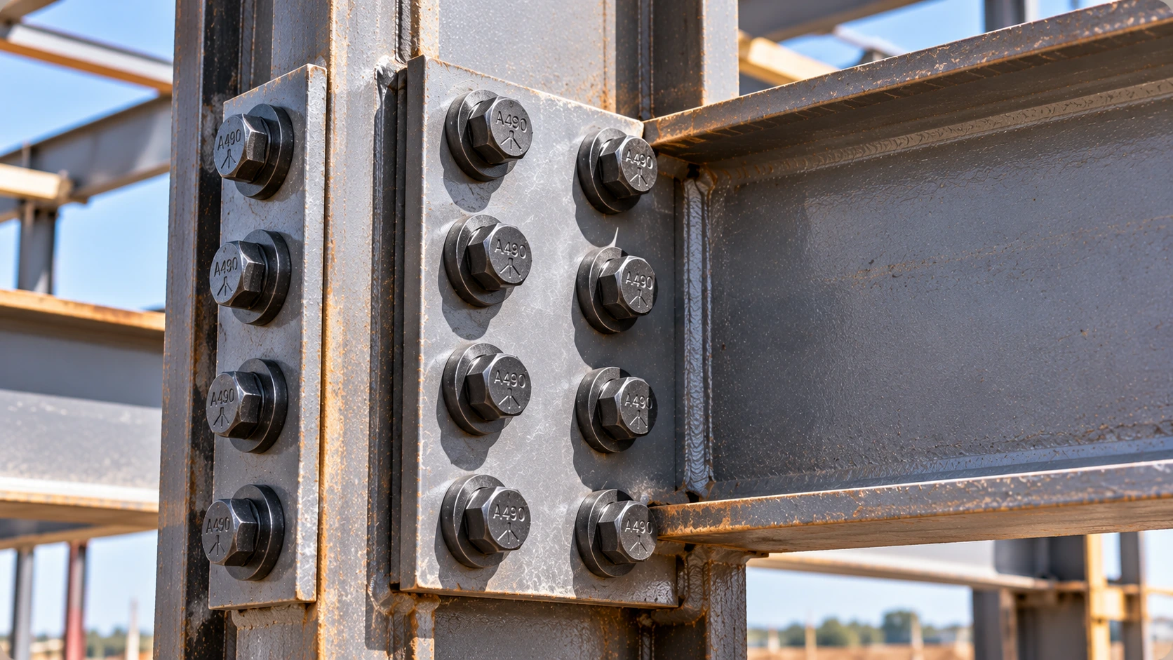
A490 bolts connect beams, columns, braces, gussets and splice plates where the design calls for the Group 150 strength level, in buildings, industrial frames and bridges.
Heavy Hex Bolt Configuration
The head and nut are heavy hex, and the bolt is supplied with matched nuts and hardened washers. Do not confuse an A490 bolt with a general-purpose bolt or a foundation anchor rod. See the Anchor Bolt Grade Chart for anchor rods.
ASTM A490 vs. ASTM F3125 Grade A490
The old standard, the new standard and how they relate.
ASTM A490 was withdrawn in 2016 and consolidated into ASTM F3125/F3125M, which replaces six standards: A325, A325M, A490, A490M, F1852 and F2280. A490 survives as Grade A490, so the current wording is “ASTM F3125 Grade A490.” ASTM lists F3125/F3125M-26 as the current edition, active as of July 31, 2026, although your project may specify an earlier adopted edition.
Historical ASTM A490
The old standalone specification covered heavy-hex structural bolts of 150 ksi minimum tensile strength from 1/2 through 1-1/2 in., with strict coating restrictions. Many drawings and articles still cite it.
Current ASTM F3125 Specification
F3125 covers bolts in two strength grades (120 and 150 ksi), two types and two styles. Grades A325, A490, F1852 and F2280 are the inch grades. The inch and SI systems are separate, and mixing values from the two can result in nonconformance.
Grade and Material Classification
| Item | Grade A490 |
|---|---|
| Minimum strength | 150 ksi |
| Style | Heavy hex |
| Type 1 | Alloy steel or alloy steel with boron |
| Type 3 | Weathering steel |
| Size range | 1/2 to 1-1/2 in. |
A490 Bolt Diameter Chart
Fractional, decimal and metric values for 1/2 to 1-1/2 in.
The nine standard inch diameters run from 1/2 to 1-1/2 in. Converting an inch diameter to millimeters does not turn an A490 bolt into an A490M metric bolt.
| Nominal diameter | Decimal inches | Millimeters | Body diameter, maximum (in.) |
|---|---|---|---|
| 1/2 in. | 0.500 | 12.70 | 0.515 |
| 5/8 in. | 0.625 | 15.88 | 0.642 |
| 3/4 in. | 0.750 | 19.05 | 0.768 |
| 7/8 in. | 0.875 | 22.23 | 0.895 |
| 1 in. | 1.000 | 25.40 | 1.022 |
| 1-1/8 in. | 1.125 | 28.58 | 1.149 |
| 1-1/4 in. | 1.250 | 31.75 | 1.277 |
| 1-3/8 in. | 1.375 | 34.93 | 1.404 |
| 1-1/2 in. | 1.500 | 38.10 | 1.531 |
Fractional and Decimal Sizes
For general fractional bolt sizes, see the US Bolt Sizes Chart.
Metric Conversions
🧮 Conversion
Example: 3/4 in. = 25.4 × 0.750 = 19.05 mm. These are rounded dimensional conversions, not interchangeable A490M designations. See the Bolt Diameter Chart for general diameters.
Nominal vs. Actual Diameter
Nominal diameter is a designation. A manufactured body is measured within the tolerance in ASME B18.2.6, and the maximum body diameter in the table is slightly above the nominal size.
A490 Heavy Hex Head Dimensions
Why a 3/4 in. bolt needs a 1-1/4 in. wrench.
ASME B18.2.6 gives nominal values and tolerances for the heavy-hex head. A 3/4 in. A490 bolt has a nominal head width of 1-1/4 in. across flats, so the wrench is much larger than the shank. A heavy-hex head is 1/8 in. wider across flats than a standard hex head of the same bolt diameter.
| Bolt | Across flats, basic (in.) | Across flats, max / min (in.) | Across corners, max / min (in.) | Head height, basic (in.) | Head height, max / min (in.) |
|---|---|---|---|---|---|
| 1/2 in. | 7/8 | 0.875 / 0.850 | 1.010 / 0.969 | 5/16 | 0.323 / 0.302 |
| 5/8 in. | 1-1/16 | 1.062 / 1.031 | 1.227 / 1.175 | 25/64 | 0.403 / 0.378 |
| 3/4 in. | 1-1/4 | 1.250 / 1.212 | 1.443 / 1.383 | 15/32 | 0.483 / 0.455 |
| 7/8 in. | 1-7/16 | 1.438 / 1.394 | 1.660 / 1.589 | 35/64 | 0.563 / 0.531 |
| 1 in. | 1-5/8 | 1.625 / 1.575 | 1.876 / 1.796 | 39/64 | 0.627 / 0.591 |
| 1-1/8 in. | 1-13/16 | 1.812 / 1.756 | 2.093 / 2.002 | 11/16 | 0.718 / 0.658 |
| 1-1/4 in. | 2 | 2.000 / 1.938 | 2.309 / 2.209 | 25/32 | 0.813 / 0.749 |
| 1-3/8 in. | 2-3/16 | 2.188 / 2.119 | 2.526 / 2.416 | 27/32 | 0.878 / 0.810 |
| 1-1/2 in. | 2-3/8 | 2.375 / 2.300 | 2.742 / 2.622 | 15/16 | 0.974 / 0.902 |
Width Across Flats
This is the wrench size. A 1 in. A490 bolt has a 1-5/8 in. head across flats, so it needs a 1-5/8 in. socket or wrench.
Width Across Corners
The corner-to-corner width governs tool and edge clearance and is larger than the across-flats value.
Head Height and Tolerances
The basic head height is a nominal reference. Real heads fall between the minimum and maximum shown.
A490 Bolt Thread Size and Pitch
UNC coarse threads and the pitch formula.
A490 bolts use the Unified National Coarse (UNC) series with a 2A thread fit. The number after the hyphen is threads per inch (TPI).
UNC Thread Chart
| Bolt | UNC thread | Threads per inch | Pitch (in.) | Pitch (mm) | Tensile stress area (in²) |
|---|---|---|---|---|---|
| 1/2 in. | 1/2-13 | 13 | 0.0769 | 1.95 | 0.142 |
| 5/8 in. | 5/8-11 | 11 | 0.0909 | 2.31 | 0.226 |
| 3/4 in. | 3/4-10 | 10 | 0.1000 | 2.54 | 0.334 |
| 7/8 in. | 7/8-9 | 9 | 0.1111 | 2.82 | 0.462 |
| 1 in. | 1-8 | 8 | 0.1250 | 3.17 | 0.606 |
| 1-1/8 in. | 1-1/8-7 | 7 | 0.1429 | 3.63 | 0.763 |
| 1-1/4 in. | 1-1/4-7 | 7 | 0.1429 | 3.63 | 0.969 |
| 1-3/8 in. | 1-3/8-6 | 6 | 0.1667 | 4.23 | 1.155 |
| 1-1/2 in. | 1-1/2-6 | 6 | 0.1667 | 4.23 | 1.405 |
Thread Pitch Formula
🧮 Pitch
3/4-10 UNC example: P = 1/10 = 0.100 in. = 2.54 mm. For thread identification, see the UNC Thread Chart, Thread Size Chart and Thread Pitch Chart.
UNC Is Not Metric
A 3/4-10 UNC bolt is not interchangeable with an M20 metric thread. The pitches (2.54 mm and 2.5 mm) and diameters (19.05 mm and 20 mm) are close but different, so mixed hardware will not fit or perform correctly.
A490 Structural Bolt Thread Length
Shorter than a general-purpose heavy-hex bolt, by design.
Structural bolts use a standardized short thread length. It keeps the plain shank in the shear plane when grip is controlled, which is why thread length differs from the general-purpose formula. Standard A490 structural bolts are not fully threaded, and a fully threaded A490 is not a standard product.
Standard Thread Length
| Bolt | Structural thread length (in.) | General heavy hex, 6 in. or less (2D + 1/4) (in.) |
|---|---|---|
| 1/2 in. | 1 | 1.25 |
| 5/8 in. | 1-1/4 | 1.50 |
| 3/4 in. | 1-3/8 | 1.75 |
| 7/8 in. | 1-1/2 | 2.00 |
| 1 in. | 1-3/4 | 2.25 |
| 1-1/8 in. | 2 | 2.50 |
| 1-1/4 in. | 2 | 2.75 |
| 1-3/8 in. | 2-1/4 | 3.00 |
| 1-1/2 in. | 2-1/4 | 3.25 |
Threaded and Unthreaded Shank
Overall bolt length, thread length, unthreaded body and the thread transition are four different things. Thread length does not change with bolt length, so a 3/4 × 3-1/4 bolt and a 3/4 × 5 bolt both have 1-3/8 in. of thread.
Shear Plane Considerations
Whether the shear plane crosses threads (N) or the plain shank (X) changes the design shear strength. Bolts with thread lengths or dimensions that differ from the specification may be ordered under A354 or A449, but ASTM notes those are not exact equivalents. A fully threaded variant marked “T” exists only for A325, and nonstandard dimensions are marked “S”. Do not assume fully threaded A490 bolts are standard products.
A490 Bolt Length and Grip Selection
Grip, washers and allowances decide the length.
Nominal bolt length is measured from under the head to the end of the bolt, so it excludes head height. The required length is the grip plus washers plus a tabulated allowance for the nut and thread projection. Length selection also depends on thread configuration and length tolerances.
Measuring Bolt Length
🧮 Required Bolt Length
Variables: G = steel grip (total connected thickness, no washers), tcomponents = separately counted washers and indicators (5/32 in. per ordinary F436 washer, 5/16 in. per beveled washer), ad = allowance for the bolt diameter. Round up to the next 1/4 in. (1/2 in. above 6 in.).
Grip and Washer Allowances
| Bolt diameter | Added length ad (in.) |
|---|---|
| 1/2 in. | 11/16 |
| 5/8 in. | 7/8 |
| 3/4 in. | 1 |
| 7/8 in. | 1-1/8 |
| 1 in. | 1-1/4 |
| 1-1/8 in. | 1-1/2 |
| 1-1/4 in. | 1-5/8 |
| 1-3/8 in. | 1-3/4 |
| 1-1/2 in. | 1-7/8 |
Worked Length Example
Selecting a 3/4 in. A490 Bolt
What it means: Verify available lengths, thread engagement and the assembly components. The bolt end must be flush with or beyond the nut face.
Do not assume every A490 bolt has the same thread position for every nominal length. Length tolerances are minus values: up to 6 in., 1/2 and 5/8 in. bolts are up to 0.12 in. short, 3/4 to 1 in. up to 0.19 in. short and 1-1/8 to 1-1/2 in. up to 0.25 in. short. Plate dimensions for grip come from the Steel Plate Thickness Chart.
A490 Type 1 vs. Type 3
Alloy steel or weathering steel, same size and strength group.
Type 1 and Type 3 are material classifications. Both follow the Grade A490 strength level and the heavy-hex dimensions.
| Property | Type 1 | Type 3 |
|---|---|---|
| Material | Alloy steel or alloy steel with boron | Weathering steel |
| Nominal geometry | Standard A490 dimensions | Standard A490 dimensions |
| Strength group | Group 150 | Group 150 |
| Chemistry basis | Composition limits in F3125 | Composition A or B, or a corrosion index of 6 or greater |
| Nuts | A563 Grade DH | A563 Grade DH3 |
| Washers | F436 Type 1 | F436 Type 3 |
Alloy Steel and Weathering Steel
Type 3 is weathering steel designed to form a protective patina in suitable wet-dry outdoor exposure. It is not stainless steel, and it does not remove the need to evaluate the exposure conditions. Type 3 assemblies use matching Type 3 nuts and washers.
A490 Mechanical Properties
Tensile and yield strength, hardness and testing.
F3125 sets the mechanical requirements for Grade A490. The values below come from the specification tables for machined specimens and hardness.
| Property | Requirement |
|---|---|
| Minimum tensile strength | 150 ksi |
| Maximum tensile strength | 173 ksi |
| Minimum yield strength | 130 ksi |
| Elongation in 4D, minimum | 14 percent |
| Reduction of area, minimum | 40 percent |
| Hardness, Brinell | 311 to 352 HB |
| Hardness, Rockwell C | 33 to 38 HRC |
Heat Treatment and Testing
Bolts are quenched in oil and tempered at not less than 800°F. Each lot is tested for tensile strength, proof load and hardness. The 150 ksi grades also get magnetic particle inspection and carburization and decarburization checks, and manufacturers provide test reports when specified.
Material Strength Is Not Connection Strength
The 150 ksi minimum tensile strength is a material specification value. It is not the allowable load of a bolt or a connection. Bolt shear, bolt tension, pretension and connected-plate limit states are separate checks.
A490 Bolt Hole Size Chart
Standard, oversize and slotted holes from RCSC Table 3.1.
RCSC 2025 Table 3.1 lists nominal hole dimensions. Standard holes are 1/16 in. larger than the bolt through 7/8 in. and 1/8 in. larger from 1 in. up. These are structural steel holes. They are not concrete anchor drill-bit sizes or general machine-bolt clearance holes, which are covered in the Clearance Hole Size Chart.
| Bolt diameter | Standard hole | Oversized hole | Short slot (width × length) | Long slot (width × length) |
|---|---|---|---|---|
| 1/2 in. | 9/16 in. | 5/8 in. | 9/16 × 11/16 in. | 9/16 × 1-1/4 in. |
| 5/8 in. | 11/16 in. | 13/16 in. | 11/16 × 7/8 in. | 11/16 × 1-9/16 in. |
| 3/4 in. | 13/16 in. | 15/16 in. | 13/16 × 1 in. | 13/16 × 1-7/8 in. |
| 7/8 in. | 15/16 in. | 1-1/16 in. | 15/16 × 1-1/8 in. | 15/16 × 2-3/16 in. |
| 1 in. | 1-1/8 in. | 1-1/4 in. | 1-1/8 × 1-5/16 in. | 1-1/8 × 2-1/2 in. |
| 1-1/8 in. | 1-1/4 in. | 1-7/16 in. | 1-1/4 × 1-1/2 in. | 1-1/4 × 2-13/16 in. |
| 1-1/4 in. | 1-3/8 in. | 1-9/16 in. | 1-3/8 × 1-5/8 in. | 1-3/8 × 3-1/8 in. |
| 1-3/8 in. | 1-1/2 in. | 1-11/16 in. | 1-1/2 × 1-3/4 in. | 1-1/2 × 3-7/16 in. |
| 1-1/2 in. | 1-5/8 in. | 1-13/16 in. | 1-5/8 × 1-7/8 in. | 1-5/8 × 3-3/4 in. |
Standard Holes
Hole Clearance Example
What it means: Radial clearance is an ideal concentric geometry result, not a manufacturing tolerance.
Oversized Holes
Used only where the joint type and design permit, and they are not interchangeable with standard holes.
Short and Long Slots
Slots allow adjustment. The slot direction, which plies may be slotted and the washer requirements come from RCSC and the connection design.
A490 Bolt Spacing and Edge Distance
AISC minimums and why diameter alone is not enough.
Bolt diameter alone does not set the hole layout. AISC requires a minimum center-to-center spacing of 2⅔ bolt diameters and prefers 3d. Edge distance runs from the center of a hole to the edge of the connected part, and end distance is the same measurement in the direction of force. Hole type, plate thickness, bearing, tearout and the bolt group geometry all matter.
| Bolt | Minimum spacing 2⅔d | Preferred spacing 3d | Min. edge at sheared edge (standard hole) | Min. edge at rolled or thermally cut edge |
|---|---|---|---|---|
| 1/2 in. | 1-1/3 in. | 1-1/2 in. | 7/8 in. | 3/4 in. |
| 5/8 in. | 1-2/3 in. | 1-7/8 in. | 1-1/8 in. | 7/8 in. |
| 3/4 in. | 2 in. | 2-1/4 in. | 1-1/4 in. | 1 in. |
| 7/8 in. | 2-1/3 in. | 2-5/8 in. | 1-1/2 in. | 1-1/8 in. |
| 1 in. | 2-2/3 in. | 3 in. | 1-3/4 in. | 1-1/4 in. |
Center-to-Center Spacing
For a 3/4 in. bolt the minimum is 2 in. and the preferred spacing is 2-1/4 in. For layout help, see the Bolt Pattern Calculator.
Edge and End Distance
Values depend on hole type and edge condition. Do not publish one universal spacing or edge rule as a complete design method.
Connected Steel Requirements
A correct bolt diameter does not guarantee adequate plate bearing, tearout or block shear. Check plate sizes in the Steel Plate Thickness Chart.
A490-Compatible Nuts
Nut grade and style matter as much as thread size.
F3125 recommends ASTM A563 Grade DH heavy-hex nuts for Type 1 A490 bolts and Grade DH3 for Type 3. An ASTM A194 Grade 2H heavy-hex nut may replace a DH nut on Type 1 A490 bolts. If coated 2H nuts are used, the same coating, thread and lubrication requirements apply as for DH nuts. An ordinary nut with matching thread diameter is not automatically acceptable.
| A490 bolt | Recommended nut | Suitable alternative | Washer |
|---|---|---|---|
| Type 1 | ASTM A563 Grade DH | ASTM A194 Grade 2H | F436 Type 1 |
| Type 3 | ASTM A563 Grade DH3 | Per ASTM F3125 and RCSC | F436 Type 3 |
ASTM A563 and Alternatives
DH nuts match A490 strength. Bolt, nut and washer should be supplied and used as a matched assembly.
Heavy Hex Nut Dimensions
Heavy-hex nuts share the head width across flats shown above. Nominal nut thicknesses include 39/64 in. for 5/8 in., 47/64 in. for 3/4 in. and 55/64 in. for 7/8 in. See the Nut Size Chart for general nut dimensions.
Thread and Coating Compatibility
The nut thread must match the bolt UNC thread, and F3125 requires bolts and nuts to be coated by the same process, with no mixed processes in a lot.
A490 Hardened Washer Requirements
F436 washers and where they go.
ASTM F436/F436M hardened washers are used with A490 assemblies, Type 1 washers with Type 1 bolts and Type 3 washers with Type 3 bolts. Where washers go depends on the joint, the installation method, the hole type and the component configuration. RCSC Section 6 sets the requirements, and the 2025 edition adds ASTM F3394 backup and reaction washers.
| Bolt size (in.) | Inside diameter (in.) | Outside diameter (in.) | Thickness (in.) |
|---|---|---|---|
| 1/2 | 0.531 | 1.063 | 0.097 to 0.177 |
| 5/8 | 0.688 | 1.313 | 0.122 to 0.177 |
| 3/4 | 0.812 | 1.469 | 0.122 to 0.177 |
| 7/8 | 0.938 | 1.750 | 0.136 to 0.177 |
| 1 | 1.125 | 2.000 | 0.136 to 0.177 |
| 1-1/8 | See ASTM F436 | See ASTM F436 | See ASTM F436 |
| 1-1/4 | 1.375 | 2.500 | 0.136 to 0.177 |
| 1-3/8 | 1.531 | 2.750 | 0.136 to 0.177 |
| 1-1/2 | 1.625 | 3.000 | 0.136 to 0.177 |
ASTM F436 Washers and Placement
For other washer types, see the Washer Size Chart.
Special Hole Configurations
Oversized and slotted holes can need washers or plate washers that a snug-tightened standard-hole joint does not. Check RCSC for the exact requirement.
A490 Bolt Head Markings
Grade, manufacturer and traceability.
F3125 requires the grade and type marking and the manufacturer’s mark on the bolt head, in separate and distinct locations. Heavy-hex A490 bolts are marked “A490,” and twist-off F2280 assemblies carry an “A490TC” or alternate “A490” mark. Marking must remain visible after coating, and Type 3 bolts may carry additional distinguishing marks at the manufacturer’s option.
- Grade identification: the A490 mark on the head.
- Manufacturer markings: the maker’s mark.
- Traceability: each lot has a unique lot number, test reports and package marking (grade, type, style, size and lot).
Markings Need Documentation
Head markings alone do not demonstrate every part of specification compliance. For 150 ksi bolts, the manufacturer’s test report also includes the certification that any coating has been qualified for use on 150 ksi bolts, including hydrogen embrittlement testing.
A490 Minimum Bolt Pretension
Group 150 values from the 2025 RCSC specification.
RCSC 2025 Table 5.2 gives the specified minimum bolt pretension for pretensioned and slip-critical joints. Group 144 and Group 150 share one column, which is the A490 column. A 3/4 in. A490 bolt has a minimum specified pretension of 35 kips for those joint conditions.
Group 150 Pretension Chart
| Nominal diameter | Minimum pretension, Group 150 |
|---|---|
| 1/2 in. | 15 kips |
| 5/8 in. | 24 kips |
| 3/4 in. | 35 kips |
| 7/8 in. | 49 kips |
| 1 in. | 64 kips |
| 1-1/8 in. | 80 kips |
| 1-1/4 in. | 102 kips |
| 1-3/8 in. | 121 kips |
| 1-1/2 in. | 148 kips |
Pretension vs. Strength
Minimum pretension is a clamping requirement. It is not bolt tensile resistance, a failure load or the allowable load of the connection.
Verification Requirements
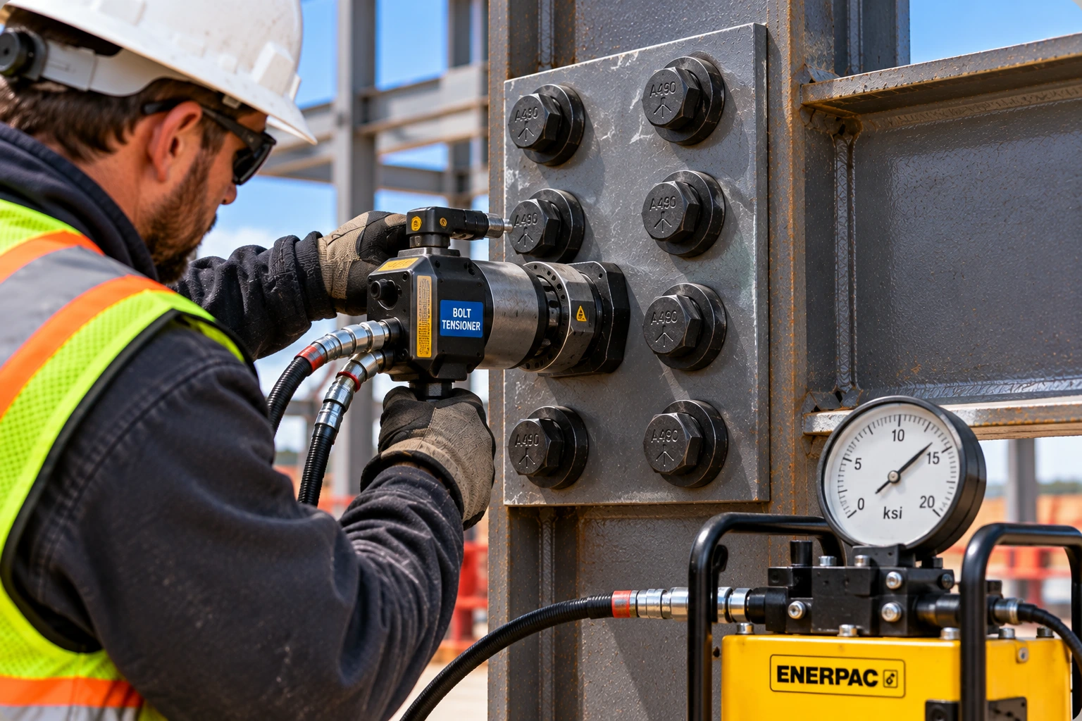
RCSC requires pre-installation verification testing of the bolting assembly, the pretensioning method and the tools, using a bolt tension measuring device (BTMD).
Equipment for Your Project
Affiliate disclosure: As an Amazon Associate, ConcreteCalculate earns from qualifying purchases. We may also earn a commission from other affiliate links at no additional cost to you.
A490 Bolt Torque vs. Pretension
Why a torque value does not tell you the bolt tension.
No universal torque chart can guarantee the specified A490 pretension. Most wrench effort goes into friction at the threads and under the nut, and the friction varies with coating, lubrication, thread condition and handling. A simplified relationship is:
🧮 Torque and Clamping Force
Variables: T = applied torque, K = approximate nut factor, F = axial clamping force, d = nominal bolt diameter. K changes with friction, coating, lubrication and assembly condition, so do not recommend an installation torque from an assumed K. For general-purpose torque references, see the Bolt Torque Chart and Bolt Torque Calculator. Those are not RCSC procedures.
Torque and Friction
For the same tension, a higher nut factor needs proportionally more torque. Lubricants, coatings, reuse and weather exposure all shift the result.
Installation Methods and RCSC Requirements
RCSC 2025 recognizes the turn-of-nut method, the twist-off tension-control bolt method, the direct tension indicator method and the combined method. The calibrated wrench method was withdrawn in the 2025 edition. The combined method still uses a calibrated wrench for the initial torque followed by a specified rotation.
A490 Structural Joint Types
Snug-tightened, pretensioned and slip-critical.
RCSC defines three joint types. Which one applies is a structural design decision that appears on the drawings.
| Joint type | Primary concept | Design designation |
|---|---|---|
| Snug-tightened | Plies brought into firm contact, with the tightness from a few impacts of an impact wrench or the full effort of an ironworker with a spud wrench | N or X (bearing) |
| Pretensioned | Bolt installed to the specified minimum pretension | N or X (bearing) |
| Slip-critical | Pretensioned with prepared faying surfaces, designed to resist slip | SC |
Snug-Tightened
Bolts carry shear by bearing against the hole. Snug-tightened bolts are not free of tension, and the joint type is not allowed for every condition.
Pretensioned
Pretension is required in specified conditions under RCSC and AISC. Not every A490 joint must be pretensioned.
Slip-Critical
Slip resistance depends on the clamping force and the faying-surface condition. Connection classification is determined by the structural design requirements.
A490 Bolt Shear Strength
Nominal bolt shear, one plane at a time.
Nominal shear strength per bolt per shear plane is the nominal shear stress times the gross bolt area. In AISC 360-16 Table J3.2, Group B (A490) bolts use 68 ksi with threads included in the shear plane (N) and 84 ksi with threads excluded (X). Use the current table for your edition. Rounded and unrounded stress values (for example 68 ksi versus 67.5 ksi) differ by under 1 percent.
Bolt Area
🧮 Area and Shear
Variables: Ab = gross bolt area (in2), Fnv = nominal shear stress (ksi), Rn = nominal shear strength per shear plane (kips).
Thread Location
| Bolt | Gross area Ab (in²) | Rn threads included (68 ksi), kips | Rn threads excluded (84 ksi), kips |
|---|---|---|---|
| 1/2 in. | 0.1963 | 13.35 | 16.49 |
| 5/8 in. | 0.3068 | 20.86 | 25.77 |
| 3/4 in. | 0.4418 | 30.04 | 37.11 |
| 7/8 in. | 0.6013 | 40.89 | 50.51 |
| 1 in. | 0.7854 | 53.41 | 65.97 |
| 1-1/8 in. | 0.9940 | 67.59 | 83.50 |
| 1-1/4 in. | 1.2272 | 83.45 | 103.08 |
| 1-3/8 in. | 1.4849 | 100.97 | 124.73 |
| 1-1/2 in. | 1.7671 | 120.17 | 148.44 |
Worked Shear Example
3/4 in. A490 Bolt in Single Shear
What it means: This is an individual bolt illustration, not the capacity of the connection. Joint length, single or double shear, bearing, tearout, block shear and net section also apply.
A490 Bolt Tensile Strength
Nominal tension, and why 150 ksi is not the design stress.
Use the structural design tensile stress, not the material minimum tensile strength. For Group 150 bolts in AISC 360-16 the nominal tensile stress is 113 ksi, while the material minimum tensile strength is 150 ksi.
Nominal Tensile Resistance
🧮 Nominal Tension
Variables: Fnt = nominal tensile stress (113 ksi for Group 150 in this example), Ab = gross bolt area.
Worked Tension Example
3/4 in. A490 Bolt in Tension
What it means: This is not a universal safe working load. It ignores prying and connected-material failure modes.
Combined Loading
Shear and tension often act together, and AISC Chapter J requires an interaction check. Prying action can add tension, and plate failure modes can control before the bolt does.
A490 vs. A325 Structural Bolts
Group 150 against Group 120.
A490 and A325 are different grades in the same F3125 specification. Compare the grade data here and see the A325 Bolt Size Chart for the Grade A325 details.
| Property | A325 | A490 |
|---|---|---|
| RCSC strength group | Group 120 | Group 150 |
| Minimum tensile strength | 120 ksi | 150 ksi |
| Minimum yield strength | 92 ksi | 130 ksi |
| Standard head geometry | Heavy hex | Heavy hex |
| Common thread series | UNC | UNC |
| 3/4 in. minimum pretension | 28 kips | 35 kips |
| 1 in. minimum pretension | 51 kips | 64 kips |
| Nominal diameter range | 1/2 to 1-1/2 in. | 1/2 to 1-1/2 in. |
| Material types | Type 1, Type 3 | Type 1, Type 3 |
| Nuts | A563 DH, or other permitted grades | A563 DH or A194 2H (Type 1) |
Selection and Substitution
Higher strength does not automatically justify substitution. Switching grades can change the design resistance, the required pretension, the nuts and washers, the coatings and the inspection requirements. Do not substitute without design and specification approval. For the broad grade comparison, see the Bolt Grade Chart and the Structural Bolt Size Chart.
A490 vs. ASTM A354 Grade BD
When a bolt with A490-level strength needs a different configuration.
ASTM A354 Grade BD is a quenched and tempered alloy steel bolt grade with mechanical properties equal to A490. Unlike A490, A354 is not restricted to heavy-hex structural geometry, so it is used where the F3125 configuration does not fit: nonstandard thread lengths, other head styles, threaded rods and anchor bolts, and diameters above 1-1/2 in. F3125 itself says bolts with different thread lengths or dimensions may be ordered under A354 or A449, and warns that these are not exact equivalents to the structural grades.
| Topic | F3125 Grade A490 | ASTM A354 Grade BD |
|---|---|---|
| Scope | Heavy-hex structural bolts and assemblies | Quenched and tempered alloy steel bolts, studs and threaded fasteners |
| Size range | 1/2 to 1-1/2 in. | 1/4 to 2-1/2 in. for BD (up to 4 in. under A354) |
| Minimum tensile strength | 150 ksi (173 ksi maximum) | 150 ksi (173 ksi maximum) |
| Minimum yield strength | 130 ksi | 130 ksi |
| Configuration | Heavy hex, standard structural thread length | Unrestricted |
| Magnetic particle test | Required for 150 ksi bolts | Not required unless a supplemental requirement is called out |
Product Specification and Thread Configuration
A354 BD is considered when nonstandard thread configurations are required, and the A354 text notes that for structural bolting above 1-1/2 in., F3125 requirements such as head size, lubricant and magnetic particle inspection should be carefully considered.
Structural Use Limitations
Do not describe A354 Grade BD as automatically equivalent to F3125 Grade A490 in structural joints. A change of specification needs engineering approval.
A490 Coatings and Hydrogen Embrittlement
The most important difference from A325.
Coatings are the biggest practical difference between A490 and A325. At 150 ksi, A490 is susceptible to hydrogen embrittlement, so hydrogen introduced by plating or pickling can cause delayed brittle fracture. That is why A490 coating rules are stricter than A325 rules.
Coating Restrictions
The old standalone A490 specification prohibited hot-dip galvanizing, mechanical deposition and electroplating with zinc. Under current F3125, Annex A1 lists the permitted coatings, and both hot-dip galvanizing (ASTM F2329) and mechanical galvanizing (ASTM B695) are shown as not qualified for Grade A490 bolts. Any coating that is not an approved system is not permitted.
Qualified Coating Systems
Zinc/aluminum corrosion-protective coatings have long been the approved route, for example ASTM F1136 Grade 3 (commercially known as Geomet). Current F3125 requires coatings for 150 ksi bolts to be qualified under IFI 144, including hydrogen embrittlement testing to ASTM F1940 (internal) and F2660 (environmental). The manufacturer’s test report must certify this. Confirm the permitted list in Annex A1 of the edition governing your project.
| Coating or finish | Status for Grade A490 | Basis |
|---|---|---|
| Plain finish | Permitted | Default if nothing is specified |
| Hot-dip galvanizing (F2329) | Not qualified | F3125 Annex A1 |
| Mechanical galvanizing (B695) | Not qualified | F3125 Annex A1 |
| Electroplated zinc | Prohibited | Hydrogen embrittlement risk |
| Zinc/aluminum corrosion-protective coating (F1136 Grade 3) | Approved when qualified | Long-standing approved route |
| Other coating systems | Only if qualified under IFI 144 with F1940 and F2660 testing | F3125 coating qualification |
Weathering Steel and Assembly Compatibility
Type 3 A490 bolts are weathering steel and rely on the patina instead of a coating. Bolts and nuts must be coated by the same process, and the nut and washer must match the coating system. For slip-critical joints, coatings on the faying surfaces are a separate qualification issue. A325 bolts have wider coating options, so do not apply A325 coating practice to A490.
A490 Bolt Applications
Where Group 150 bolts are used in steel construction.
A490 bolts are used where the design calls for the Group 150 strength level.
- Beam connections: beam-to-column connections and shear tabs. See the Steel I-Beam Chart and Steel Beam Size Chart.
- Bracing and splices: splice plates, gussets and braces, including tube members in the HSS Size Chart.
- Industrial and bridge structures: heavy frames, and bridge connections where specified.
- High-strength joints: connections of the members in the Structural Steel Shapes Chart.
A490 is not a general replacement for concrete anchor rods or for every high-strength machine bolt. For welded alternatives, see the Fillet Weld Size Chart.
How to Measure and Identify an A490 Bolt
A practical identification sequence.
Use this sequence to identify and measure an A490 bolt.
- Identify head markings. Look for the A490 grade mark and the manufacturer mark.
- Measure nominal diameter. Use calipers on the unthreaded shank.
- Measure heavy-hex width across flats. Compare with the chart, for example 1-1/4 in. for a 3/4 in. bolt.
- Measure under-head bolt length. Do not include the head.
- Determine UNC thread pitch. A thread gauge should show the UNC pitch, such as 10 TPI for a 3/4 in. bolt.
- Check the structural thread length.
- Confirm material type and finish.
- Review certification and traceability. Test reports confirm what the head cannot.
For diameter and thread details, see the chart at the top of this page and the Bolt Diameter Chart.
How to Select the Correct A490 Bolt Size
Follow the drawings, then check each component.
The diameter comes from the engineered design, not from this chart.
- Read the approved structural drawings.
- Identify the specified Grade A490 and the product type.
- Determine the required diameter.
- Check the hole type and dimensions.
- Determine the grip and the bolt length.
- Confirm the nuts and washers.
- Verify coating compatibility.
- Identify the joint installation requirements.
- Check inspection and certification requirements.
No Unapproved Substitution
Do not substitute grade or size without approval from the engineer of record. For the wider family of structural bolts, see the Structural Bolt Size Chart.
A490 Installation and Inspection
Methods, verification and reuse.
Install and inspect A490 bolts under the project specification and RCSC. Do not use a generic torque instruction.
Before Installation
Handle and store assemblies to keep them clean and lubricated, match bolts, nuts and washers by lot, and confirm the test reports and coating certification.
Pretensioning and Verification
Where pretension is specified, use an approved RCSC method (turn-of-nut, twist-off tension control, direct tension indicator or combined method) after pre-installation verification testing. Calibrated-wrench installation was withdrawn in the 2025 edition. Snug-tightening applies only where the design allows it.
Inspection and Reuse
Inspection follows the joint type. Nonconforming assemblies have a defined remedy, and bolt reuse is restricted and depends on grade, finish and joint type, so check RCSC Section 2.11 before reusing any A490 bolt.
Common A490 Bolt Mistakes
The dimension, coating and installation errors that cause the most trouble.
Outdated specification
Treating withdrawn standalone ASTM A490 as the current specification.
Dimension errors
Confusing head width with nominal diameter, measuring length over the head, or using general-purpose heavy-hex thread lengths.
Wrong hardware
Using incompatible UNC and metric hardware, or ordinary nuts and washers.
Coating mistakes
Assuming all zinc coatings are acceptable, or ignoring hydrogen embrittlement.
Type confusion
Treating Type 3 as stainless steel.
Pretension confusion
Confusing pretension with torque, or assuming every joint requires pretension.
Strength misuse
Using minimum tensile strength as an allowable load.
Shear plane errors
Ignoring threads in the shear plane.
Hole restrictions
Ignoring bolt-hole restrictions.
Grade substitution
Substituting A490 for A325 without approval.
Connected steel
Ignoring plate bearing, tearout and block shear.
Reuse
Reusing installed bolts without checking the rules.
A490 Chart Limitations and Structural Safety
Reference dimensions are not a connection design.
This chart provides dimensional and technical reference data. It does not independently establish:
- The correct bolt diameter for a new connection.
- Complete connection capacity or bolt group strength.
- The required number of bolts or safe hole spacing.
- Slip resistance.
- Approved coating substitution.
- Installation acceptance or structural design compliance.
The structural drawings, the Engineer of Record, the applicable standards and the project requirements control. Calculated and illustrative values are labeled. RCSC values are in U.S. Customary units, and RCSC strongly discourages direct conversion to SI.
A490 Bolt Size FAQs
Straight answers to the most common A490 bolt questions.
What sizes do A490 bolts come in?
Grade A490 heavy-hex bolts are furnished in nine inch sizes from 1/2 to 1-1/2 in. The metric A490M runs from M12 to M36. Standard thread lengths are listed in the chart above.
What replaced ASTM A490?
ASTM F3125/F3125M replaced the standalone A490 specification in 2016. A490 is now Grade A490 within F3125.
What is ASTM F3125 Grade A490?
It is the 150 ksi class heavy-hex structural bolt grade in ASTM F3125/F3125M, made of alloy steel (Type 1) or weathering steel (Type 3).
What is the head size of a 3/4-inch A490 bolt?
The nominal head is 1-1/4 in. across flats and 15/32 in. high.
What wrench size fits a 1-inch A490 bolt?
The head is 1-5/8 in. across flats, so a 1-5/8 in. wrench or socket fits. For tool sizes, see the Nut Size Chart.
What UNC threads do A490 bolts use?
UNC coarse threads: 1/2-13, 5/8-11, 3/4-10, 7/8-9, 1-8, 1-1/8-7, 1-1/4-7, 1-3/8-6 and 1-1/2-6.
Are A490 bolts fully threaded?
Standard structural A490 bolts are not fully threaded. They have a shortened structural thread length, such as 1-3/8 in. on a 3/4 in. bolt. Fully threaded A490 is not a standard product.
What hole size is required for a 3/4-inch A490 bolt?
A standard hole is 13/16 in. and an oversized hole is 15/16 in., per RCSC 2025 Table 3.1.
What is the tensile strength of an A490 bolt?
The minimum tensile strength is 150 ksi, with a 173 ksi maximum and a 130 ksi minimum yield strength. These are material values, not connection capacity.
What is the minimum pretension for a 3/4-inch A490 bolt?
35 kips for pretensioned and slip-critical joints under RCSC 2025.
Is A490 stronger than A325?
A490 has a higher minimum tensile strength (150 ksi against 120 ksi), and a higher minimum pretension. See the A325 Bolt Size Chart.
Can A490 replace A325?
Not automatically. Substitution changes the design resistance, pretension, hardware, coating selection and inspection, so it needs design and specification approval.
Can A490 bolts be galvanized?
Hot-dip and mechanical galvanizing are not qualified for Grade A490 because of hydrogen embrittlement, and electroplating is prohibited. Qualified zinc/aluminum coating systems are the approved route. Check F3125 Annex A1.
What is the difference between Type 1 and Type 3?
Type 1 is alloy steel. Type 3 is weathering steel. They share the same sizes and strength level, and neither is stainless steel.
What nuts and washers are required?
ASTM A563 Grade DH heavy-hex nuts (or A194 Grade 2H on Type 1 bolts) and ASTM F436 Type 1 hardened washers. Type 3 bolts use DH3 nuts and Type 3 washers.
Can A490 bolts be reused?
Reuse is restricted and depends on the grade, finish and joint type. RCSC Section 2.11 sets the rules.
How do I select A490 bolt length?
Add the grip, the washer thicknesses and the diameter allowance, then round up to the next 1/4 in. A 2 in. grip with one washer on a 3/4 in. bolt gives a preliminary 3-1/4 in. length.
Are A490 bolts suitable for concrete anchoring?
No. Grade A490 structural bolts are for steel-to-steel joints. Foundation anchor rods follow a different standard. See the Anchor Bolt Grade Chart.
Cite or Embed This Chart
📄 Print or Save This Chart as PDF
Use your browser’s print function to save the page as a PDF reference for jobsite binders and estimating folders.
Sources and Standards Used
Dimensions come from ASME B18.2.6 as published by a bolt manufacturer. Hole sizes and pretension follow the 2025 RCSC Specification. Mechanical properties, nut and washer pairings and the coating framework follow ASTM F3125, using the text of the 2021 edition, so confirm details against F3125/F3125M-26. Pitch, metric conversions, general-bolt thread lengths and illustrative shear and tension values are calculated and marked as derived.
- ASTM F3125/F3125M-26, High Strength Structural Bolts and Assemblies
- RCSC, Specification for Structural Joints Using High-Strength Bolts (June 5, 2025)
- AISC 360-22, Specification for Structural Steel Buildings
- ASME B18.2.6, Fasteners for Use in Structural Applications
- Portland Bolt, structural bolt dimensional data
- Portland Bolt, nonstandard structural bolt thread lengths