Fillet Weld Size Chart – Minimum Sizes, Leg Dimensions and Throat
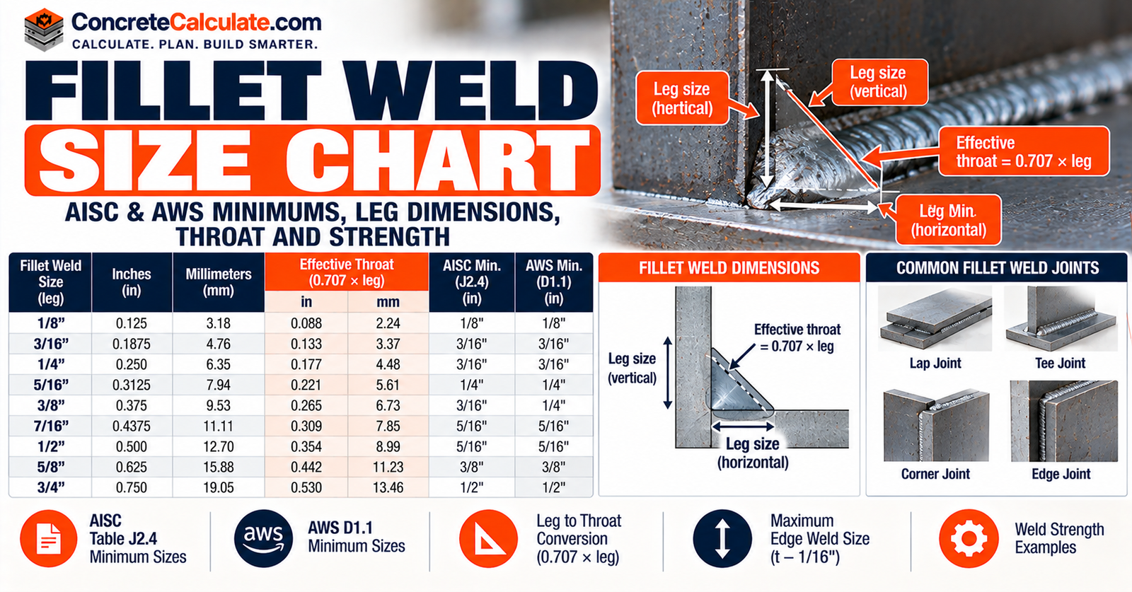
Fillet Weld Size Chart
Minimum Sizes, Leg Dimensions and Throat
Convert fillet weld leg size to effective throat, check AISC Table J2.4 and AWS D1.1 minimum sizes by connected-part thickness, verify maximum edge weld size, and review introductory strength and length calculations for structural steel connections.
 Reviewed by Muhammad Ramzan Babar, PhD Researcher (Plasma Physics) & Calculator Developer – View Profile
Important: This Is a Dimensional Reference, Not a Connection Design Tool
This chart addresses conventional carbon and low-alloy structural steel connections. Stainless steel, aluminum, sheet-metal welding, pressure piping, fatigue-sensitive structures and seismic detailing need separately qualified treatment. AISC and AWS minimum-size requirements are not identical and must not be combined into one oversimplified rule; always confirm the adopted code edition and project specification.
Fillet Weld Size Chart – Quick Reference
Three compact tables: leg-to-throat conversion, AISC minimum size by thinner-part thickness, and a navigation guide distinguishing minimum, maximum and load-required weld size.
How to Read This Chart
The leg-to-throat table assumes an equal-leg 90-degree fillet. AISC minimums use the thinner connected part; AWS D1.1 minimums involve additional welding-process, preheat and cyclic-loading qualifications that can change the controlling value. Actual weld selection depends on the applicable adopted code, edition and connection design, not this chart alone.
Standard Fillet Weld Leg Size and Effective Throat
| Leg Size | Decimal Inches | Millimeters | Theoretical Effective Throat |
|---|---|---|---|
| 1/8 in. | 0.1250 | 3.175 | 0.0884 in. |
| 3/16 in. | 0.1875 | 4.7625 | 0.1326 in. |
| 1/4 in. | 0.2500 | 6.350 | 0.1768 in. |
| 5/16 in. | 0.3125 | 7.9375 | 0.2210 in. |
| 3/8 in. | 0.3750 | 9.525 | 0.2652 in. |
| 7/16 in. | 0.4375 | 11.1125 | 0.3094 in. |
| 1/2 in. | 0.5000 | 12.700 | 0.3536 in. |
| 5/8 in. | 0.6250 | 15.875 | 0.4419 in. |
| 3/4 in. | 0.7500 | 19.050 | 0.5303 in. |
This formula assumes equal legs, a 90-degree joint, and the conventional theoretical weld profile. Skewed joints, unequal-leg welds, incomplete fusion, and special penetration provisions require different treatment.
AISC Minimum Fillet Weld Size (Table J2.4)
| Thickness of Thinner Connected Part | Minimum Fillet Weld Leg Size |
|---|---|
| Up to 1/4 in., inclusive | 1/8 in. |
| Over 1/4 in. through 1/2 in. | 3/16 in. |
| Over 1/2 in. through 3/4 in. | 1/4 in. |
| Over 3/4 in. | 5/16 in. |
Not the Same as AWS D1.1
These are the AISC Table J2.4 minimums, based on the thinner connected part. They do not establish the weld size required to carry a particular load, and they are not automatically identical to AWS D1.1 requirements, which add welding-process, preheat, and cyclic-loading qualifications. See the dedicated AWS section below before finalizing a fabrication specification.
Minimum, Maximum, and Load-Required Size: Quick Navigation
| Weld Size Concept | Governs | Where to Check |
|---|---|---|
| Minimum fabrication size | Fusion, heat input, and cracking resistance | AISC Table J2.4 or AWS D1.1 Table 7.7 |
| Maximum edge size | Avoiding overwelding at plate edges | AISC Section J2.2b |
| Load-required size | Connection strength for the calculated force | Structural design per AISC Chapter J |
What Is a Fillet Weld?
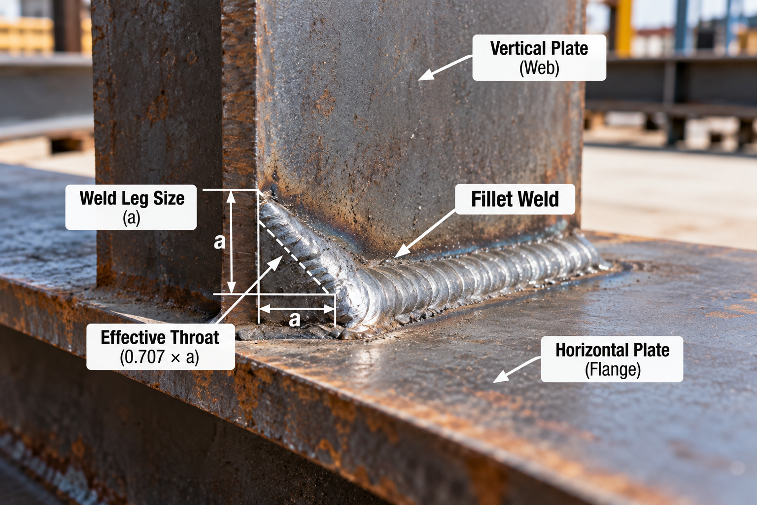
A fillet weld joins two surfaces meeting at approximately a right angle, most commonly in T-joints, lap joints, and corner joints.
- T-joints: One member meets another at a right angle, common in stiffeners and beam connections.
- Lap joints: Overlapping plates welded along the edge of the overlap.
- Corner joints: Two members meeting at an outside or inside corner.
Fillet welds are distinct from groove welds (which fuse through a prepared joint), plug welds, slot welds, and seal welds. Detailed groove-weld design is outside the scope of this chart.
Fillet Weld Anatomy: Leg, Throat, Root, Face, and Toe
| Term | What It Means | Where Measured |
|---|---|---|
| Leg size | Specified weld dimension along each face | Along the two legs of the triangular profile |
| Theoretical throat | Idealized shortest distance from root to hypotenuse | Perpendicular from root to the flat theoretical face |
| Effective throat | Throat dimension used in strength calculations | Per the governing code’s defined geometry |
| Actual throat | Measured throat of the as-built weld | Physical cross-section of the completed weld |
| Root | Point where the two members and weld meet | Innermost point of the joint |
| Face | Exposed surface of the weld | Visible weld bead surface |
| Toe | Junction between weld face and base metal | Where the bead meets the parent material |
| Weld length | Distance along the joint that is welded | Along the joint line |
Visible bead width is not necessarily equal to specified leg size or effective throat. A convex or irregular bead can appear larger than its structurally credited throat.
Fillet Weld Leg Size vs. Effective Throat
The specified leg dimension and the throat that resists structural loads are two different measurements.
Equal-Leg 90-Degree Relationship
a = w × 0.7071, where w is the leg size and a is the theoretical effective throat.
| Leg Size (w) | Calculation | Theoretical Throat (a) |
|---|---|---|
| 1/8 in. | 0.125 x 0.7071 | 0.0884 in. |
| 3/16 in. | 0.1875 x 0.7071 | 0.1326 in. |
| 1/4 in. | 0.25 x 0.7071 | 0.1768 in. |
| 5/16 in. | 0.3125 x 0.7071 | 0.2210 in. |
Excessive surface convexity does not automatically count toward the effective throat used in conventional design; the theoretical geometric profile, not the visible bead, governs the calculation.
Standard Fillet Weld Size Conversion Chart
Common sizes with fractional, decimal, metric, and theoretical-throat values.
| Metric Size | Exact Converted Inches | Nearest Fractional Size |
|---|---|---|
| 3 mm | 0.1181 in. | ~1/8 in. |
| 4 mm | 0.1575 in. | ~3/16 in. |
| 5 mm | 0.1969 in. | ~3/16 in. |
| 6 mm | 0.2362 in. | ~1/4 in. |
| 8 mm | 0.3150 in. | ~5/16 in. |
| 10 mm | 0.3937 in. | ~3/8 in. |
| 12 mm | 0.4724 in. | ~1/2 in. |
Distinguish exact metric conversions of U.S. fractional sizes from independently specified metric weld sizes on international drawings; they are close but not identical.
AISC Minimum Fillet Weld Size Chart
ANSI/AISC 360-22 Section J2.2b and Table J2.4 set the minimum fillet weld size based on the thinner connected part.
| Thickness of Thinner Connected Part | Minimum Fillet Weld Leg Size |
|---|---|
| t ≤ 1/4 in. | 1/8 in. |
| 1/4 in. < t ≤ 1/2 in. | 3/16 in. |
| 1/2 in. < t ≤ 3/4 in. | 1/4 in. |
| t > 3/4 in. | 5/16 in. |
These minimums address heat input and fusion adequacy, not the size needed to resist a particular calculated force. The minimum fabrication requirement and the load-required size are two separate checks, and the table includes a groove-weld reinforcement exception addressed in the standard itself. Verify the exact table against the current adopted edition before publication or use in a fabrication specification.
✓ Reference: ANSI/AISC 360-22, Table J2.4AWS D1.1:2025 Minimum Fillet Weld Size Requirements
AWS D1.1:2025 Clause 7.13 and Table 7.7 add conditions that AISC Table J2.4 does not include.
AISC and AWS Are Not Identical
AWS D1.1:2025 minimum-size requirements depend on base-metal thickness ranges, the welding process used, applicable preheat conditions, and whether the structure is cyclically loaded. Under specified non-low-hydrogen conditions without the prescribed preheat, the thicker connected part can control instead of the thinner part. AWS also specifies a 3/16-inch minimum for cyclically loaded structures within its relevant provisions.
| Condition | How It Affects the Minimum |
|---|---|
| Base-metal thickness range | Sets the baseline minimum, similar in structure to AISC’s table |
| Welding process | Certain processes and preheat combinations change which connected part controls |
| Preheat condition | Absence of prescribed preheat under specified conditions can shift control to the thicker part |
| Cyclic loading | AWS specifies a 3/16-inch minimum for cyclically loaded structures under its relevant provisions |
Confirm which standard, code edition, welding procedure specification (WPS), and project specification control before finalizing a minimum weld size; do not assume AISC and AWS values are interchangeable.
✓ Reference: AWS D1.1/D1.1M:2025, Clause 7.13 and Table 7.7Minimum Fillet Weld Size by Steel Plate Thickness
A practical construction lookup converting the code tables into common plate-thickness scenarios.
| Thinner-Part Thickness | Thicker-Part Thickness | Applicable Standard | Tabulated Minimum | Additional Check |
|---|---|---|---|---|
| 1/8 in. | 1/8 in. (equal) | AISC J2.4 | 1/8 in. | Confirm AWS process/preheat condition |
| 1/4 in. | 1/4 in. (equal) | AISC J2.4 | 1/8 in. | Confirm AWS process/preheat condition |
| 3/8 in. | 3/8 in. (equal) | AISC J2.4 | 3/16 in. | Confirm AWS process/preheat condition |
| 1/2 in. | 1/2 in. (equal) | AISC J2.4 | 3/16 in. | Confirm AWS process/preheat condition |
| 3/4 in. | 3/4 in. (equal) | AISC J2.4 | 1/4 in. | Confirm AWS process/preheat condition |
| 1 in. | 1 in. (equal) | AISC J2.4 | 5/16 in. | Confirm AWS process/preheat condition |
| 1/4 in. | 3/4 in. (unequal) | AISC J2.4 | 1/8 in. (based on thinner part) | AWS may weigh the thicker part differently |
No single universally applicable weld size applies to every pair of plate thicknesses; confirm the governing standard and its process-specific qualifications for each project.
Maximum Fillet Weld Size Along Plate Edges
AISC limits the maximum specified size along the edges of connected parts.
| Material Thickness | Maximum Fillet Weld Size Along Edge |
|---|---|
| Less than 1/4 in. | Equal to the material thickness |
| 1/4 in. | 1/4 – 1/16 = 3/16 in. |
| 3/8 in. | 3/8 – 1/16 = 5/16 in. |
| 1/2 in. | 1/2 – 1/16 = 7/16 in. |
| 3/4 in. | 3/4 – 1/16 = 11/16 in. |
For material thinner than 1/4 inch, the maximum is generally the material thickness. For material at least 1/4 inch thick, the ordinary maximum is the thickness minus 1/16 inch, subject to the applicable special-detailing exception. This edge limitation is distinct from welding on a broad plate face and from the separate minimum-size requirement discussed above.
✓ Reference: ANSI/AISC 360-22, Section J2.2bEqual-Leg vs. Unequal-Leg Fillet Welds
Symmetrical and asymmetrical weld geometry require different throat calculations.
Unequal-Leg Throat Formula
For an ideal right-angle triangular profile with legs w1 and w2: a = (w1 × w2) / √(w1² + w2²)
Unequal-Leg Example
The simple 0.707 multiplier is not appropriate for unequal legs; it applies only to the equal-leg 90-degree case. Unequal-leg welding is specified where access, geometry, or connection design requirements make equal legs impractical.
Concave vs. Convex Fillet Weld Profiles
Theoretical weld geometry and actual bead shape are not the same thing.
- Flat profile: Approximates the theoretical triangular shape most closely.
- Concave profile: Bead surface curves inward, potentially reducing actual throat below the theoretical value.
- Convex profile: Bead bulges outward; excess material does not automatically increase the credited effective throat.
- Underfill and overlap: Can create localized throat deficiencies even where average bead size looks acceptable.
Visual bead size alone cannot establish the correct effective throat. Profile acceptance must follow the governing welding code’s specific criteria, not a general visual impression.
Fillet Weld Effective Area Chart
Effective area relates throat and weld length: Awe = a × Le.
| Leg Size | Effective Throat (a) | Effective Area per Inch of Weld (in²/in) |
|---|---|---|
| 1/4 in. | 0.1768 in. | 0.1768 |
| 5/16 in. | 0.2210 in. | 0.2210 |
| 3/8 in. | 0.2652 in. | 0.2652 |
Geometric effective area alone does not establish available connection strength; it must be combined with the applicable weld-metal strength and resistance factors covered next.
Fillet Weld Strength Chart for E70 Filler Metal
An illustrative strength chart using 70-ksi-class filler metal and the AISC basic weld-metal stress relationship.
Basic Nominal Weld-Metal Stress
Fnw = 0.60 × FEXX. For an ordinary longitudinal fillet weld without a directional strength increase, AISC’s fillet-weld shear limit state uses φ = 0.75 (LRFD) and Ω = 2.00 (ASD).
| Leg Size | Effective Throat (a) | Nominal Strength Rn per in. (kip/in) | Design Strength φRn per in., LRFD (kip/in) |
|---|---|---|---|
| 1/4 in. | 0.1768 in. | 7.43 | 5.57 |
| 5/16 in. | 0.2210 in. | 9.28 | 6.96 |
| 3/8 in. | 0.2652 in. | 11.14 | 8.35 |
| 1/2 in. | 0.3536 in. | 14.85 | 11.14 |
This chart is illustrative for E70 filler metal and an ordinary longitudinal fillet weld under LRFD; it does not include any directional strength increase. A weld-strength value alone does not establish the adequacy of its connected plate or the complete connection; base-metal strength and other limit states must also be checked.
How to Calculate Required Fillet Weld Size
Introductory Calculation Workflow
Eccentric connections, combined loading, fatigue, and specialized seismic requirements need additional engineering beyond this introductory workflow.
Fillet Weld Size and Filler Metal Classification
Filler-metal classification influences weld-metal strength but does not automatically permit a smaller weld.
- E60, E70, and other classifications indicate electrode tensile strength, not automatic joint performance.
- Matching filler metal pairs weld-metal strength closely with base-metal strength.
- Undermatching may be used in certain qualified situations per the applicable WPS.
- Base-metal compatibility and relevant AWS filler-metal standards govern the correct selection.
A stronger electrode does not always permit a smaller weld, and not all welding processes use interchangeable classifications; the qualified WPS controls the actual combination used in production.
Fillet Weld Length Requirements
Minimum effective length, actual length, end returns, and discontinuous weld arrangements all affect design.
Minimum Length Is a Design Limitation
Under AISC provisions, the minimum length of a strength-designed fillet weld generally must be at least four times its nominal size; otherwise the effective size used in design is reduced. This is a code design limitation, not a universal recommended production weld length.
| Leg Size | Minimum Effective Length (4 x leg) |
|---|---|
| 1/4 in. | 1.0 in. |
| 3/8 in. | 1.5 in. |
| 1/2 in. | 2.0 in. |
Long Fillet Welds and Effective Length Reduction
Exceptionally long, end-loaded fillet welds cannot always be credited at their full geometric length.
AISC Length-Reduction Factor
For end-loaded fillet welds with length-to-size ratio (l/w) greater than 100: β = 1.2 – 0.002(l/w) ≤ 1.0, and effective length Leff = β × L. Where l/w exceeds 300, the effective length is capped rather than continuing to decrease linearly.
Long Weld Example
This reduction applies to end-loaded welds under the applicable provisions; do not assume the same reduction applies to every loading pattern, including welds loaded along their length in shear.
Equipment for Your Project
Affiliate disclosure: As an Amazon Associate, ConcreteCalculate earns from qualifying purchases. We may also earn a commission from other affiliate links at no additional cost to you.
Continuous vs. Intermittent Fillet Welds
| Factor | Continuous | Intermittent |
|---|---|---|
| Weld arrangement | Unbroken along the joint | Segments separated by unwelded gaps (pitch) |
| Total deposited length | Equal to joint length | Sum of individual segment lengths |
| Effective length credited | Full joint length, subject to end-loading rules | Sum of qualifying segment lengths only |
A sample specification such as a 1/4-inch intermittent fillet weld, 2-inch segments at 6-inch pitch, must clearly identify segment length and pitch. Intermittent welding cannot automatically replace a continuous structural or sealing weld; the design determines which arrangement is appropriate.
Single-Sided vs. Double-Sided Fillet Welds
- Accessible weld faces: Some joints only allow welding from one side.
- Total effective throat area: Doubling weld sides can double geometric throat area.
- Load path and eccentricity: Single-sided welds on some joints introduce eccentric loading.
- Connection symmetry: Double-sided welds can improve load distribution in some geometries.
Doubling the number of welds does not automatically double the available strength of the complete connection if the base metal, connection geometry, or other limit states govern instead of weld shear alone.
Fillet Weld Size for T-Joints, Lap Joints, and Corner Joints
| Joint Type | Typical Geometry | Main Loading Consideration | Access Constraint |
|---|---|---|---|
| T-joint | One member perpendicular to another | Shear and bending combinations | Often good access from both sides |
| Lap joint | Overlapping plates | Primarily shear along the overlap | May limit access to one side |
| Corner joint | Members meeting at an angle, often 90° | Depends on joint detail and loading direction | Can restrict welding position |
Shear versus tension, prying, and eccentric effects vary by joint configuration. A single universal size cannot be assigned solely from the joint’s name; the actual loading and geometry govern.
Fillet Weld Symbols and Drawing Interpretation
AWS A2.4:2020 is the primary reference for structural welding symbols.
| Symbol Element | What It Indicates |
|---|---|
| Arrow side | Weld is on the side the arrow points to |
| Other side | Weld is on the side opposite the arrow, symbol above the reference line |
| Leg size | Placed to the left of the fillet weld symbol |
| Weld length and pitch | Placed to the right of the symbol for intermittent welds |
| All-around symbol | Circle at the junction of the reference line and arrow |
| Field weld symbol | Flag indicating the weld is made at the job site rather than in the shop |
How to Read Fillet Weld Size and Length Callouts
| Example Callout | Meaning |
|---|---|
| 1/4 (arrow side only) | 1/4-inch leg fillet weld on the arrow side of the joint |
| 1/4 (both sides, symbol above and below) | 1/4-inch leg fillet weld on both sides of the joint |
| 1/4 x 3/8 (unequal legs) | Unequal-leg weld with legs of 1/4 inch and 3/8 inch |
| 1/4, 2-6 (intermittent) | 1/4-inch leg, 2-inch-long segments at 6-inch pitch |
Common Reading Mistake
A “1/4-inch” callout on a fillet weld symbol specifies the leg size, not the effective throat. Confusing these two values leads to overestimating actual weld capacity by roughly 40 percent.
Fillet Weld Size for Structural Steel Connections
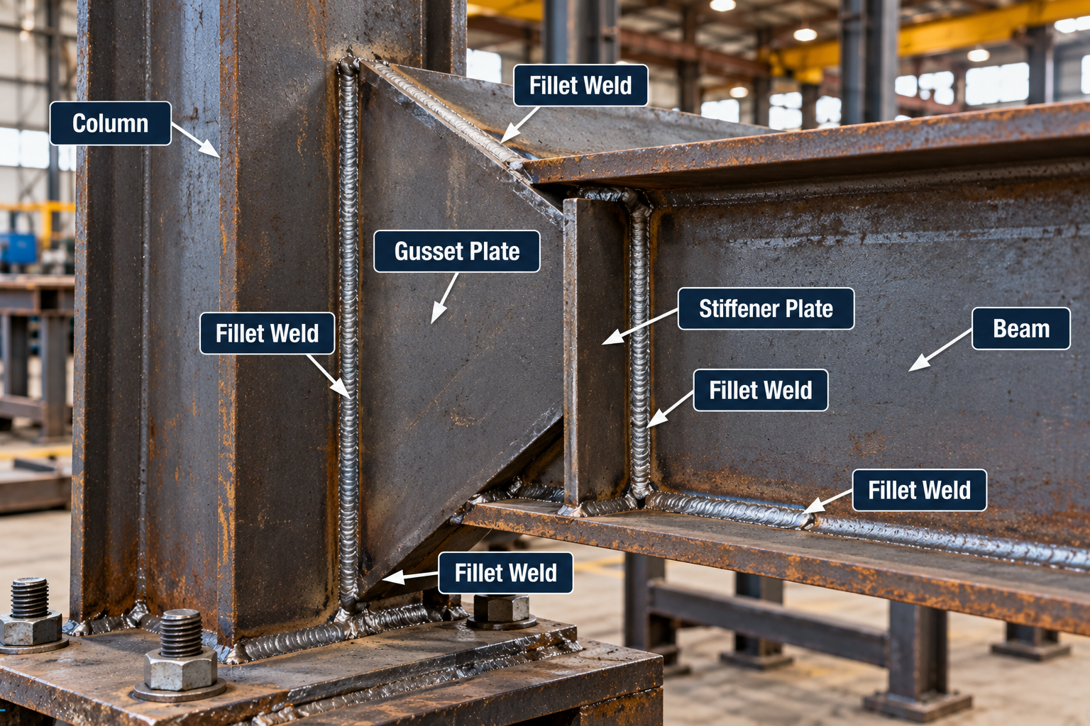
Common applications include beam-to-column shear connections, stiffeners, gusset plates, built-up members, and column base-plate details.
Weld size is driven by connection forces, geometry, required weld length, access, material grade, and the governing specification, not by the connection type’s name alone. See the Steel I-Beam Chart for beam dimensions used in these connections, the Structural Steel Shapes Chart for member selection, and the Base Plate Calculator for base-plate sizing.
Fillet Weld Size for Thin vs. Thick Steel
Welding thin connected parts and relatively thick structural plates involve different fusion requirements, edge limitations, heat input considerations, burn-through risk, preheat needs, multi-pass welding, and restraint. The governing minimum size can differ between AISC and AWS depending on process conditions, as discussed above. A specific welding-current or heat-input setting cannot be prescribed from plate thickness alone; the qualified WPS controls.
Welding Position, Process, and Pass Size
- Positions: Flat, horizontal, vertical, and overhead affect achievable weld size and workmanship.
- Processes: SMAW, GMAW, FCAW, and SAW have different deposition characteristics.
- Pass arrangement: Single-pass versus multi-pass fabrication depends on required size and process capability.
The approved WPS, AWS requirements, welding variables, and qualified procedure control what is permitted in production, not merely the leg dimension shown on a reference chart.
How to Measure and Inspect Fillet Weld Size
- Use an appropriate fillet weld gauge designed for the joint geometry.
- Measure leg size along each face of the weld.
- For unequal-leg welds, measure each leg separately rather than assuming symmetry.
- Check profile (flat, concave, convex) against the applicable acceptance criteria.
- Ensure the weld face is accessible and clean before measurement.
AWS D1.1:2025 contains dedicated inspection provisions and acceptance requirements; there is no single universal defect-tolerance table that applies to every project and loading category.
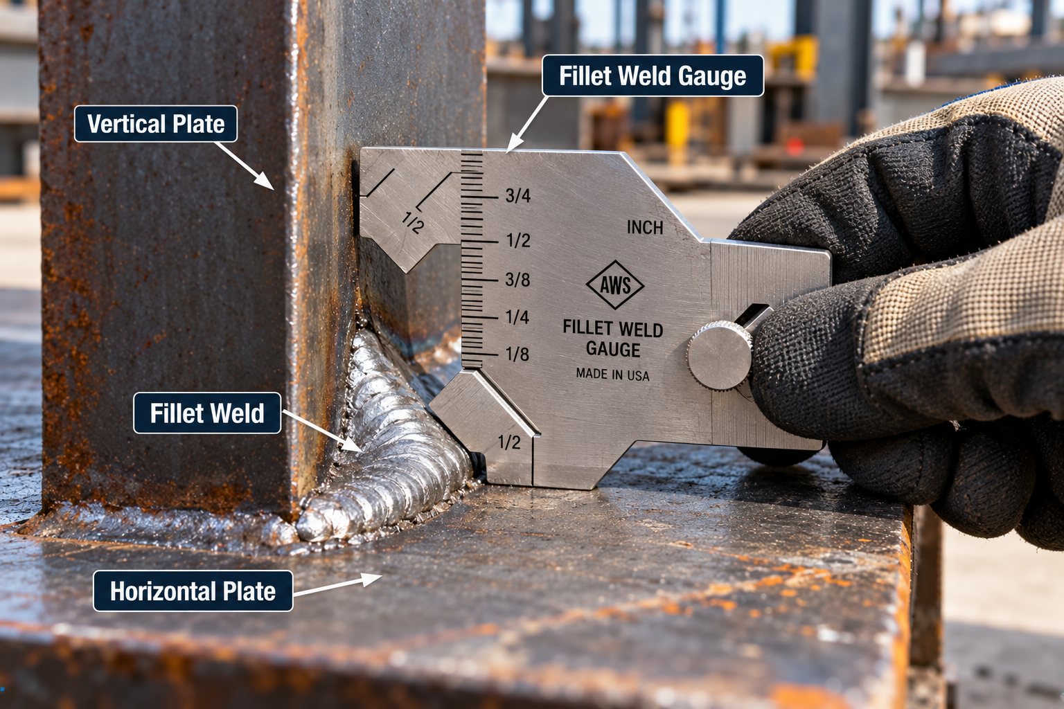
Common Fillet Weld Defects and Undersized Welds
| Condition | Description | Why It Matters |
|---|---|---|
| Undersize | Leg or throat smaller than specified | Reduces available strength below the design assumption |
| Incomplete fusion | Weld metal does not fully bond to base metal | Creates a weak plane in the joint |
| Undercut | Groove melted into base metal at the toe | Reduces effective base-metal section |
| Overlap | Weld metal extends beyond the fusion line without bonding | Can trap stress concentrations |
| Excessive convexity | Bead bulges well beyond the theoretical profile | Extra metal does not add credited throat |
| Porosity/cracks | Internal or surface discontinuities | Can reduce strength or initiate failure |
| Insufficient length | Weld shorter than the code-required minimum | Effective size used in design may be reduced |
Not every surface imperfection makes a weld unacceptable; acceptance depends on the governing code, loading category, and approved inspection criteria for the specific project.
Fillet Weld Volume, Weight, and Material Estimating
Idealized Cross-Section and Volume
For an equal-leg triangular profile: A = w² / 2, and V = A × L, where A is idealized cross-sectional area and L is weld length.
1/4-Inch Weld Over 10 Feet
Actual weld-metal usage depends on bead contour, penetration, process deposition efficiency, starts and stops, and wastage. Do not present this theoretical deposited volume as the exact purchased consumable quantity.
How to Select the Correct Fillet Weld Size
- Start with the approved connection design and identify the governing standard and edition.
- Determine connected-part thicknesses, loading, material grade, filler metal, weld access, and effective length.
- Check calculated strength against the applied load.
- Verify minimum fabrication size under the applicable code.
- Verify maximum edge size where welding along a plate edge.
- Confirm weld length requirements, including any long-weld reduction.
- Confirm welding process and WPS requirements.
- Review cyclic or seismic provisions if applicable.
- Confirm inspection criteria for the project.
A welder can verify size, length, and profile from the drawing and WPS; the responsible engineer’s connection design determines the required size, standard, and applicable exceptions.
Common Fillet Weld Size Mistakes
Confusing leg size with throat
The specified size is the leg dimension, not the smaller effective throat.
Using the wrong controlling plate thickness
AISC uses the thinner connected part; AWS conditions can differ.
Treating AISC and AWS minima as identical
AWS adds process, preheat, and cyclic-loading qualifications AISC’s base table does not include.
Ignoring AWS process and preheat qualifications
These can shift which connected part controls the minimum size.
Specifying welds larger than permitted at plate edges
Overwelding an edge exceeds the AISC maximum edge-size limitation.
Assuming minimum fabrication size supplies adequate strength
Minimum size and load-required size are separate checks.
Using full geometric length when a reduction applies
Long, end-loaded welds may require the beta reduction factor.
Overestimating a concave weld or counting convexity as throat
Neither visual impression substitutes for the theoretical or measured effective throat.
Neglecting connected-part strength
Weld strength alone does not establish complete connection adequacy.
Misreading intermittent pitch
Segment length and pitch are both required to interpret the callout correctly.
Assuming stronger filler metal always allows a smaller weld
The qualified WPS and design method determine actual permitted sizing.
Estimating deposited metal from an ideal bead without adjustment
Real deposition includes contour, penetration efficiency, and wastage.
Fillet Weld Size Chart Limitations
This chart is a reference for common structural steel fillet-weld geometry and selected code provisions.
What This Chart Does Not Establish
It cannot independently establish connection adequacy, WPS qualification, fabrication acceptance, fatigue performance, seismic detailing, or suitability for stainless steel, aluminum, pressure equipment, and other specialized applications. The applicable adopted code, project specifications, approved drawings, welding procedures, and qualified inspection requirements control.
Fillet Weld Size FAQs
Download Fillet Weld Size Chart PDF
Use your browser print function to save this reference as a PDF for shop binders, inspection checklists, and training materials.