LVL Span Chart 2026 – Sizes, Depths, Products & Load Guide
LVL Span Chart
Sizes, Depths, Products & Load Guide
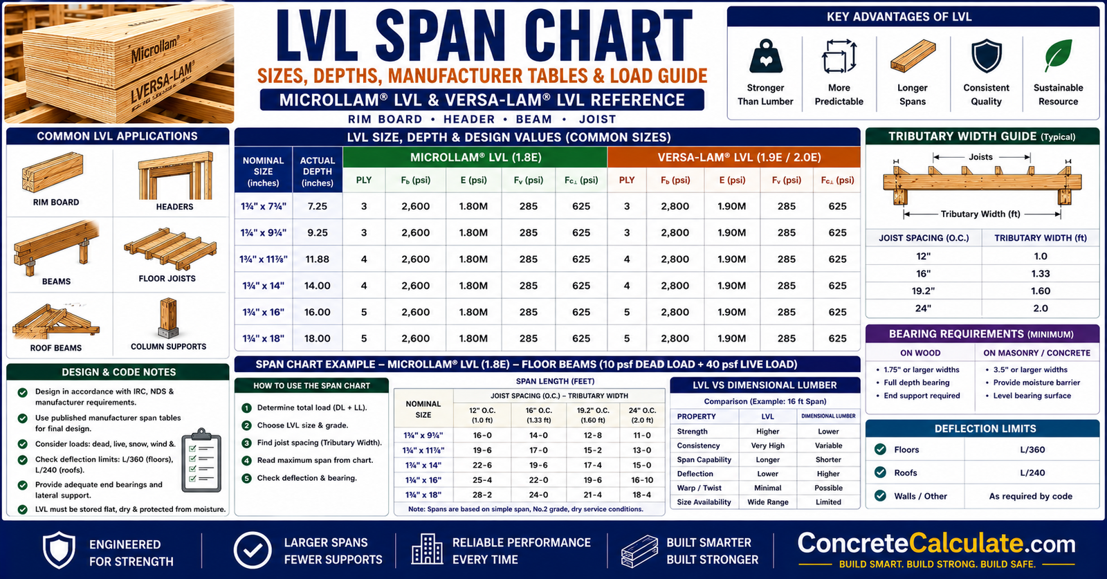
A detailed LVL sizing reference organized around real manufacturer product lines rather than a single generic number. LVL is an engineered product, and every manufacturer publishes its own dimensions, design values, and span tables.
Table of Contents
- Master LVL Span Chart
- What Is LVL?
- LVL Span vs LVL Size
- LVL Size Chart
- LVL Span by Depth
- LVL Span by Number of Plies
- LVL Span by Load
- Total Load vs Load per Linear Foot
- LVL Span by Application
- LVL Floor Beam Span Chart
- LVL Header Span Chart
- LVL Roof Beam Span Chart
- LVL Ridge Beam Span Chart
- LVL Deck Beam Span Chart
- LVL Garage Beam Span Chart
- LVL Span by Manufacturer
- Microllam LVL Span Chart
- Versa-Lam LVL Span Chart
- LVL 2.0E Span Chart
- LVL Design Values
- LVL Span and Bending Strength
- LVL Span and Deflection
- LVL Span and Shear
- LVL Span and Bearing Requirements
- LVL Span and Tributary Width
- LVL Span and Point Loads
- LVL Span for Multiple Floors
- LVL Span and Snow Load
- LVL Span and Dead Load
- LVL Span and Live Load
- LVL Span and Roof Pitch
- LVL Span vs Dimensional Lumber
- LVL vs Glulam
- LVL vs PSL
- LVL vs I-Joist
- Built-Up LVL Beam Guide
- LVL Connection and Fastening
- LVL Notching and Drilling
- LVL Beam Camber
- LVL Span for Exterior Applications
- LVL Span for Garage Applications
- LVL Span for Basement Beams
- LVL Span for Open Concept Remodeling
- LVL Span for Decks
- LVL Span for Roof Ridge Beams
- Visual LVL Span Guide
- How to Read an LVL Span Chart
- How to Calculate LVL Beam Size
- LVL Span Worked Examples
- Common LVL Sizing Mistakes
- FAQ, 15 Questions
- Download PDF
Master LVL Span Chart
LVL is a proprietary engineered product, so this master chart is organized by manufacturer and product line rather than combined into one generic number. Weyerhaeuser publishes 2.0E Microllam LVL header and beam sizes at 1.75 inch width across depths from 5.5 to 20 inches, while Boise Cascade publishes separate Versa-Lam span and size charts across its own width and depth offerings. Treat the figures below strictly as educational reference points illustrating how these charts are structured, not as a substitute for the current published manufacturer table.
| Product line | Common width | Available depth range | Typical grade designation | Design basis |
|---|---|---|---|---|
| Weyerhaeuser Microllam LVL | 1.75 in | 5.5 in to 20 in (up to 24 in in deep beam guides) | 2.0E | Weyerhaeuser specifier and beam design guides |
| Boise Cascade Versa-Lam LVL | 1.75, 3.5, 5.25, 7 in | 7.25 in to 24 in depending on width and region | 1.8E 2650, 2.1E 3100, 2.0E variants | Boise Cascade Western and Eastern design guides, BC Calc |
| Other approved LVL products | Varies by manufacturer | Varies by manufacturer | Varies by manufacturer | That manufacturer’s current design guide and code evaluation report |
What Is LVL?
Laminated veneer lumber (LVL) is a structural composite lumber product, not simply a larger piece of ordinary sawn lumber.
How LVL is manufactured
Thin wood veneers are peeled from logs, dried, graded, and bonded together with a structural adhesive under heat and pressure to form long, dimensionally consistent billets that are then cut to size.
Veneer orientation
All veneers run with their grain in the same, longitudinal direction, unlike plywood, which cross laminates veneer layers. This orientation is what gives LVL its high strength and stiffness along its length.
Structural composite lumber
LVL belongs to a family of engineered wood products, alongside PSL and LSL, that are manufactured to controlled, product specific design values rather than graded from natural growth characteristics.
Why LVL suits long spans
Because manufacturing removes natural defects such as knots and reduces variability, LVL can often achieve greater consistent strength and stiffness for a given depth than typical sawn lumber, useful for longer spans and heavier loads.
LVL Span vs LVL Size
Span capacity is a function of width, depth, ply count, and the applicable design values together, not any one dimension alone.
| Dimension changed | Effect on section properties | Practical impact |
|---|---|---|
| Thickness or width increase | Section modulus and moment of inertia increase linearly with width | Helps capacity, but less efficiently than depth |
| Depth increase | Section modulus increases with depth squared, moment of inertia with depth cubed | Major effect on bending resistance and stiffness |
| Additional plies | Increases overall width when properly connected | Can increase capacity and load sharing, subject to fastening design |
Because depth affects section modulus by the square and moment of inertia by the cube, a relatively modest increase in LVL depth can substantially raise both bending resistance and stiffness, generally a more efficient path to added capacity than adding width alone.
LVL Size Chart
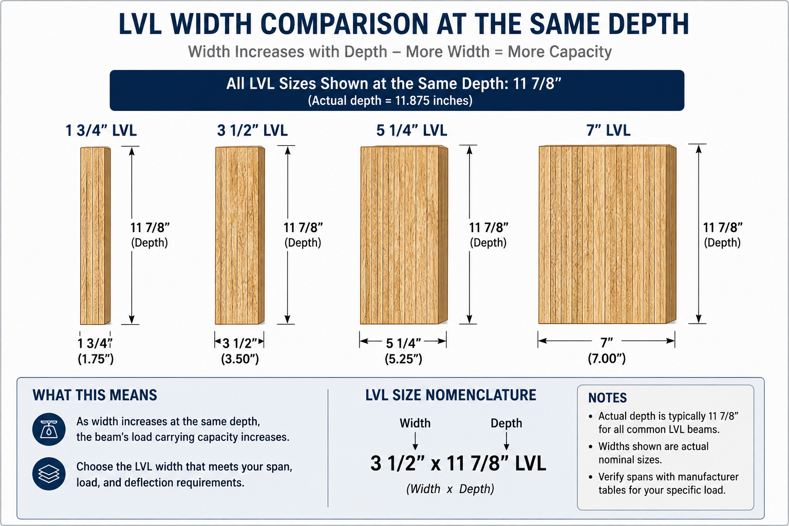
Common LVL widths and the depths typically offered at each width vary by manufacturer. The reference groupings below reflect commonly published Microllam and Versa-Lam width categories.
| Width category | Commonly available depths (varies by manufacturer) | Typical use |
|---|---|---|
| 1 3/4 inch LVL | 5.5, 7.25, 9.25, 9.5, 11.25, 11.875, 14, 16, 18, 20 in (Microllam range) | Single ply headers and beams |
| 3 1/2 inch LVL | 7.25 to 24 in depending on manufacturer and region | Single member equivalent to doubled 1 3/4 in plies |
| 5 1/4 inch LVL | 7.25 to 24 in depending on manufacturer and region | Heavier single member option, reduces ply count |
| 7 inch LVL | 7.25 to 24 in depending on manufacturer and region | Heaviest common single member width, long spans or high loads |
LVL Span by Depth
Depths shown reflect commonly available Microllam and Versa-Lam depth options. Only reference depths actually offered by the specific product being specified.
| Depth | Commonly offered by | Typical application |
|---|---|---|
| 5.5 in | Microllam | Shallow headers over smaller openings |
| 7.25 in | Microllam, Versa-Lam | Common header and light beam depth |
| 9.25 in | Microllam | Floor beam and header applications |
| 9.5 in | Microllam, Versa-Lam | Common floor beam depth |
| 11.25 in | Microllam | Common floor beam depth |
| 11.875 in (11 7/8 in) | Microllam, Versa-Lam | Common floor beam depth, matches 12 in joist framing |
| 14 in | Microllam, Versa-Lam | Longer spans or heavier loads |
| 16 in | Microllam, Versa-Lam | Longer spans, garage headers, ridge beams |
| 18 in | Microllam, Versa-Lam | Long spans and heavy loads |
| 20 in | Microllam, Versa-Lam | Longest common depth before deep beam design guides apply |
Depth availability reflects Weyerhaeuser’s published 2.0E Microllam LVL header and beam size range and Boise Cascade’s published Versa-Lam depth offerings, both of which extend further with deep beam design guides for 22 and 24 inch depths in certain products.
LVL Span by Number of Plies
Additional plies increase overall member width and can increase load sharing capacity, but only when properly connected according to the manufacturer’s fastening requirements.
| Configuration | Effective width example (1.75 in plies) | Key requirement |
|---|---|---|
| Single LVL | 1.75 in | Standard single member design |
| Double LVL | 3.5 in | Plies must be fastened per manufacturer schedule to share load |
| Triple LVL | 5.25 in | Fastening pattern, bearing, and connections must all be verified |
| Multi ply LVL | Varies | May require through bolts rather than nails or screws alone at higher ply counts |
LVL Span by Load
Numerical span values are only meaningful when tied to a specific product’s published design table under stated assumptions. The categories below are organizational reference points, not universal capacities.
| Uniform load category | Typical planning context |
|---|---|
| 500 plf | Light residential floor or roof condition, still requires full manufacturer table check |
| 1,000 plf | Common moderate residential beam loading range |
| 1,500 plf | Wider tributary width or multi story load common at this level |
| 2,000 plf | Deeper LVL or additional plies frequently needed |
| 2,500 plf | Higher capacity product or multi ply configuration commonly evaluated |
| 3,000 plf | Professional structural design and manufacturer sizing software strongly recommended |
LVL Total Load vs Load per Linear Foot
These two figures describe different things and are frequently confused when reading LVL span tables.
| Term | Definition | Example |
|---|---|---|
| Total load | The full weight the LVL carries, in pounds | 10,000 lb total on the beam |
| Uniform load | Load spread evenly along the beam, in pounds per linear foot (plf) | 1,000 lb per ft over a 10 ft span equals 10,000 lb total |
The same 10,000 lb total load can produce very different maximum moment, shear, and deflection depending on whether it is spread out evenly or concentrated at one point. Manufacturer span tables are typically built around uniform load assumptions and separately address point loads.
LVL Span by Application
LVL Floor Beam Span Chart
LVL floor beams support floor joists in residential floors, open plan spaces, basements, and crawlspaces. Tributary width, determined by joist span and spacing on each side of the beam, converts the floor’s area load into the line load the LVL must carry. Wider open plan layouts increase both joist span and beam tributary width simultaneously.
LVL Header Span Chart
LVL headers support the load above window and door openings in load bearing walls, including cases where multiple floors bear on the same wall line. See the Door Header Size Calculator and the Beam Size Chart for related header and beam sizing guidance.
LVL Roof Beam Span Chart
LVL roof beams support rafters or trusses and must account for roof dead load, snow load, and, where applicable, unbalanced or drifted snow conditions. Ridge beams are a distinct application covered in the next section.
LVL Ridge Beam Span Chart
A structural ridge beam is different from a simple ridge board.
| Element | Function |
|---|---|
| Ridge board | Non structural member that only provides a nailing surface where rafters meet, typical of conventional rafter framing with rafter ties |
| Structural ridge beam | Load bearing member designed to carry rafter reactions and transfer them to posts or walls, common where cathedral or vaulted ceilings eliminate rafter ties |
A structural ridge beam must be sized for the actual rafter reactions, roof geometry, and snow load, then bear on posts, walls, or columns with adequate capacity down to the foundation.
LVL Deck Beam Span Chart
Where a manufacturer approves LVL for exterior deck applications, the beam must still be sized for deck joist tributary width, deck loads, and it must transfer load to posts and footings. See the Deck Beam Span Chart resources, Deck Joist Span Chart, Deck Load Chart, and Deck Footing Size Chart resources.
LVL Garage Beam Span Chart
| Garage opening width | Sizing consideration |
|---|---|
| 8 ft | Common single door width, moderate header demand |
| 10 ft | Larger single or compact double opening |
| 12 ft | Common double door width, increased jamb reactions |
| 14 ft | Wider double opening, higher concentrated reactions |
| 16 ft | Standard two car opening, often requires deeper or multi ply LVL |
| 18 ft | Wide opening, frequently needs engineered product and professional design |
| 20 ft and wider | Substantial concentrated and distributed loads, professional design essential |
Garage headers and beams can carry substantial concentrated loads from roof structure or upper floors bearing above the opening, in addition to the distributed load across the opening width.
LVL Span by Manufacturer
There is no single universal LVL product. Manufacturers publish their own design properties, span tables, installation requirements, connection requirements, and product dimensions.
Weyerhaeuser Microllam LVL
Weyerhaeuser provides dedicated Microllam LVL specifier documentation, including standard beam and header sizes plus deep beam design guides for 22 and 24 inch depths.
Boise Cascade Versa-Lam LVL
Boise Cascade publishes dedicated Versa-Lam span and size charts by region (Western and Eastern guides) and provides BC Calc software for product specific sizing.
Other LVL products
Other manufacturers publish their own code evaluation reports and design guides. Always use the documentation for the specific brand and product being installed.
Microllam LVL Span Chart
| Property | 2.0E Microllam LVL |
|---|---|
| Standard width | 1.75 in |
| Standard depths | 5.5, 7.25, 9.25, 9.5, 11.25, 11.875, 14, 16, 18, 20 in |
| Deep beam depths | 22 and 24 in, per dedicated deep beam design guide |
| Grade designation | 2.0E |
| Typical applications | Headers, floor beams, garage beams, ridge beams |
Reflects Weyerhaeuser’s published 2.0E Microllam LVL header and beam sizing documentation and its separate design guide for 22 and 24 inch deep beams. Always confirm current allowable spans and loads using Weyerhaeuser’s current specifier guide or sizing software.
Versa-Lam LVL Span Chart
| Property | Versa-Lam LVL (varies by grade) |
|---|---|
| Standard widths | 1.75, 3.5, 5.25, 7 in |
| Standard depths | 7.25, 9.5, 11.875, 14, 16, 18 in and up to 24 in depending on width, grade, and region |
| Common grade designations | 1.8E 2650, 2.1E 2800, 2.1E 3100, 2.3E 3100 (varies by region and product) |
| Typical applications | Headers, floor beams, garage beams, multi ply girders |
Reflects Boise Cascade’s published Versa-Lam Western and Eastern design guides. Boise Cascade explicitly maintains separate span and size charts by region and grade rather than one combined generic chart, and provides BC Calc for project specific analysis.
LVL 2.0E Span Chart
2.0E is a grade designation referring to a modulus of elasticity, E, of approximately 2.0 million psi, indicating relative stiffness.
LVL Design Values
| Design value | Meaning | Why it matters |
|---|---|---|
| Fb | Bending design value | Sets allowable bending stress for strength design |
| E | Modulus of elasticity, stiffness | Controls deflection under a given load and span |
| Fv | Shear design value | Governs capacity near supports and short, heavily loaded spans |
| Fc perpendicular | Compression perpendicular to grain | Limits allowable bearing stress at supports |
| Ft | Tension design value, where applicable | Relevant for certain connection and continuous member conditions |
Published reference tables list example bending design values for structural composite lumber products such as LVL 2.0E, PSL 2.0E, and LSL 1.55E at differing Fb levels, illustrating that products with a similar E designation can still have different bending design values. Always use the specific manufacturer’s current published design values for the exact product being specified.
LVL Span and Bending Strength
Bending stress in an LVL beam equals bending moment divided by section modulus. Because section modulus depends on width and the square of depth, deeper members or additional properly connected plies reduce bending stress for a given moment. The calculated bending stress must remain within the manufacturer’s adjusted allowable Fb for the selected product, grade, width, and depth.
LVL Span and Deflection
A beam can satisfy bending strength requirements and still fail a deflection based serviceability check.
| Common deflection limit | Typical context |
|---|---|
| L/240 | Total load deflection, common general floor and roof reference |
| L/360 | Live load deflection, common general floor reference |
| L/480 | Live load deflection for floors supporting brittle finishes or sensitive partitions |
The allowable span for a given LVL is frequently governed by deflection rather than bending strength, particularly at longer spans, so both checks must be performed.
LVL Span and Shear
Shear stress is typically highest near the supports rather than at midspan. Short spans with heavy loads are more likely to be governed by shear than by bending. The manufacturer’s published shear design value, Fv, along with any adjustment factors for depth, must be checked in addition to bending and deflection. Notching or drilling near supports can significantly affect shear capacity and must follow manufacturer limits.
LVL Span and Bearing Requirements
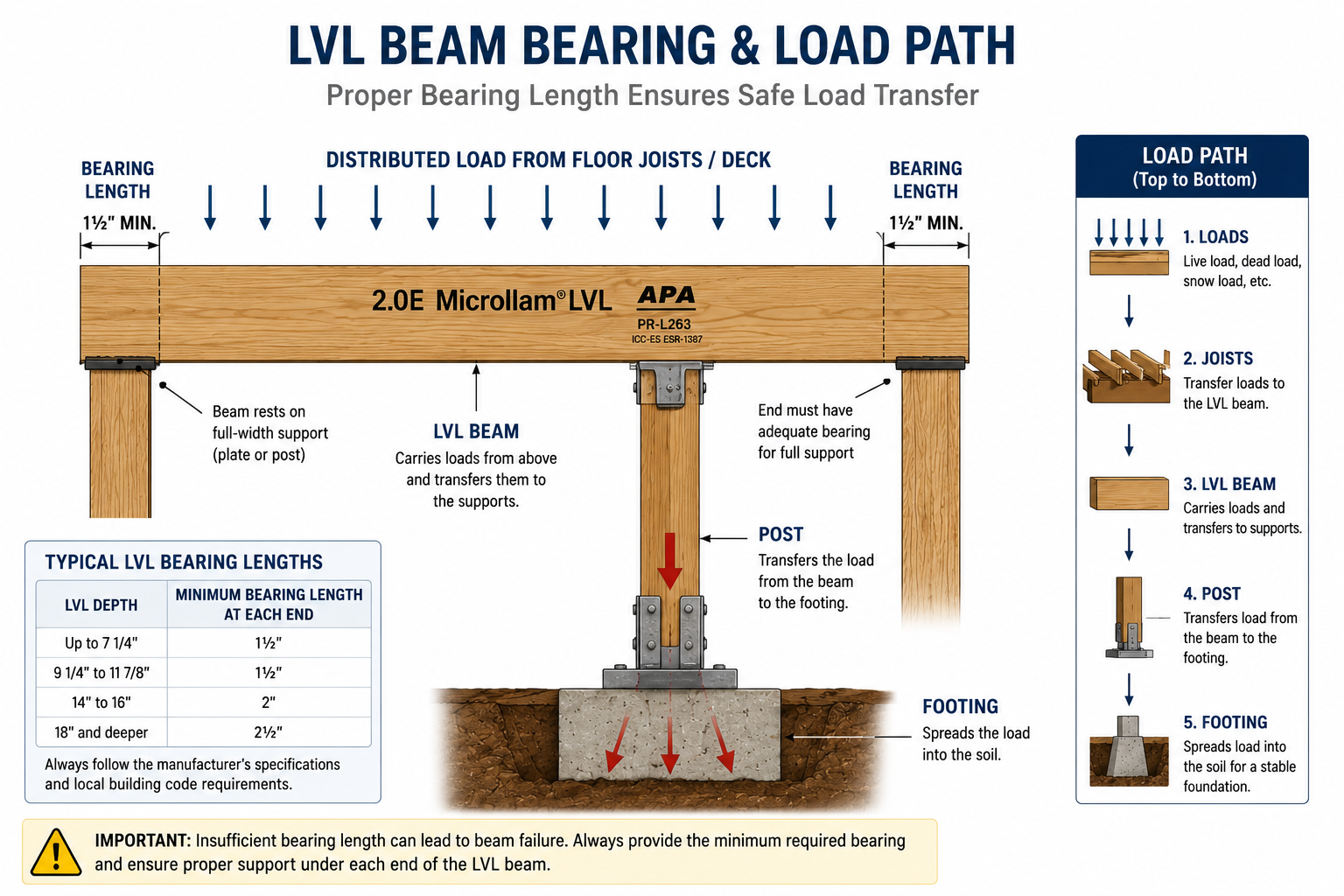
Users often focus only on span and overlook the bearing condition at the supports, which is an equally important check.
| Bearing element | What to verify |
|---|---|
| End bearing | Minimum bearing length per manufacturer requirements at each end support |
| Intermediate bearing | Adequate bearing length and alignment where the LVL bears on an interior support |
| Support width | Post, wall, or beam width beneath the LVL must provide the required bearing area |
| Compression perpendicular to grain | Bearing stress must remain within the manufacturer’s allowable Fc perpendicular value |
| Posts and walls | Must be sized to carry the LVL reaction down to the foundation |
| Bearing plates | May be required to distribute concentrated reactions, especially on steel or masonry supports |
LVL Span and Tributary Width
Tributary width is the width of floor or roof area assumed to deliver load to a given LVL. Some manufacturer guides note that when floor joists are continuous over the LVL beam rather than simply spanning to it, the effective tributary width should be increased by a manufacturer specified factor, illustrating why product specific guidance matters even for this basic calculation.
LVL Span and Point Loads
A uniform load spreads evenly along the LVL. A point load acts at a specific location and can govern the design even when the total load appears similar to a uniform load case.
| Point load source | Typical cause |
|---|---|
| Beam reaction | End reaction from another beam framing into the LVL |
| Post load | Column or post load transferred from an upper level |
| Roof truss reaction | Concentrated bearing point from a truss |
| Concentrated load | Any load applied over a small area rather than distributed along the span |
A generic uniform load LVL table may not be appropriate when significant point loads exist, since point loads should be modeled at their actual location for an accurate bending and shear check.
LVL Span for Multiple Floors
| Supported structure | Relative load level |
|---|---|
| Roof only | Lowest, subject to snow load |
| One floor | Low to moderate |
| Two floors | Moderate to high |
| Floor plus roof | High |
| Multiple levels | Highest, professional structural design essential |
The same clear span can require a very different LVL size depending on how many levels of structure it actually supports, since each additional level adds cumulative load to the same beam.
LVL Span and Snow Load
Ground snow load, roof snow load, snow accumulation, and unbalanced or drifted snow are location specific design inputs set by the applicable local building code. An LVL supporting a roof in a high snow region should never be sized from a generic low load assumption intended for a milder climate. There is no single nationwide snow load value that applies everywhere.
LVL Span and Dead Load
Dead load includes flooring, roofing, sheathing, wall weight, ceiling finishes, mechanical systems, and the LVL’s own self weight. These loads act continuously and must be included in every load combination alongside live and snow loads.
LVL Span and Live Load
Live load varies by occupancy and use, including residential floors, storage areas, decks, and garages. The applicable building code sets the minimum required design live load for each occupancy. Make the design basis explicit, including which load combination governs, for every span figure referenced.
LVL Span and Roof Pitch
Roof geometry affects tributary loading, rafter reactions, snow load accumulation, and the loading delivered to a ridge beam. Steeper or more complex roof geometries can change how load is distributed to a supporting LVL compared with a simple low slope roof, so roof pitch should be accounted for in the load calculation rather than assumed constant.
LVL Span vs Dimensional Lumber
| Feature | LVL | Dimensional lumber |
|---|---|---|
| Manufacturing | Engineered, bonded veneers | Sawn from a single log |
| Strength consistency | Higher consistency | Grade dependent, more variable |
| Long spans | Excellent | More limited |
| Availability | Product dependent, by manufacturer | Widely available |
| Design tables | Manufacturer specific | Species and grade tables (NDS Supplement) |
| Cost | Usually higher | Usually lower |
See the Beam Size Chart and Lumber Span Chart for dimensional lumber specific guidance.
LVL vs Glulam
| Feature | LVL | Glulam |
|---|---|---|
| Manufacturing | Thin veneers bonded with grain aligned | Thicker sawn laminations bonded together |
| Available dimensions | Manufacturer specific standard widths and depths | Can be manufactured in larger or curved custom shapes |
| Strength | High and consistent for its depth | High, with product specific combination symbols |
| Span | Excellent for typical residential to light commercial spans | Excellent, often used for longer or architectural spans |
| Appearance | Utilitarian, often concealed | Can be specified for exposed architectural appearance |
| Applications | Headers, beams, ridge beams, joists via LVL flanges | Beams, columns, arches, exposed structural applications |
LVL vs PSL
| Product | Manufacturing basis |
|---|---|
| LVL | Bonded wood veneers, grain aligned longitudinally |
| PSL | Bonded long wood strands (parallel strand lumber) |
| LSL | Bonded shorter wood strands (laminated strand lumber) |
All three are structural composite lumber products, but each has a distinct manufacturing process and its own published design values. For example, reference tables list differing bending design values across LVL 2.0E, PSL 2.0E, and LSL 1.55E products, underscoring that these are not interchangeable simply because they share a similar E designation.
LVL vs I-Joist
These products are frequently confused but generally serve different roles.
| Product | Typical role |
|---|---|
| LVL | Beam, header, ridge beam, girder |
| I-Joist | Floor joist, roof rafter or joist |
LVL is commonly used where a solid, high capacity rectangular section is needed to carry concentrated reactions from joists, trusses, or posts above. I-joists are optimized for repetitive floor or roof framing at closer spacing and are not typically used as a beam supporting multiple joist reactions.
Built-Up LVL Beam Guide
Multiple LVL members can be fastened together to form a built up beam.
Ply arrangement
Plies must be aligned flush and installed per the manufacturer’s orientation requirements.
Fastening
Nailing, screw, or bolt patterns must follow the manufacturer’s specified schedule for the given ply count and depth.
Load sharing
Plies only share load as assumed in design when properly connected; improper fastening can leave one ply carrying more than intended.
Bearing and connections
Bearing length and any beam to post connections must be sized for the full multi ply reaction, not a single ply’s share.
LVL Connection and Fastening
Connection requirements are configuration specific.
LVL Notching and Drilling
LVL should never be cut, notched, or drilled without following manufacturer specific guidance.
Holes for plumbing or electrical penetrations, notches, and any field modification can significantly reduce strength if they exceed the manufacturer’s permitted size, location, and spacing limits. Always consult the specific product’s installation guide before making any cut or penetration.
LVL Beam Camber
Some LVL beams, particularly longer span members, may be manufactured or specified with a slight camber, an intentional upward curve, so that the beam approaches level once in service and under sustained load. Correct installation orientation relative to any manufactured camber is important and should follow the manufacturer’s labeling and installation instructions.
LVL Span for Exterior Applications
LVL Span for Garage Applications
Garage door headers and beams often carry both distributed roof or floor load and concentrated reactions from the structure above, in addition to spanning a wide opening. See the LVL Garage Beam Span Chart section above for opening width considerations.
LVL Span for Basement Beams
Basement LVL beams typically support floor joists above, often bearing on foundation walls or interior posts. Confirm bearing capacity of the foundation wall or pier below, in addition to the beam’s own span and load design.
LVL Span for Open Concept Remodeling
Replacing a load bearing wall with an LVL changes the structural load path and should be designed for the actual loads involved, not assumed from a simple table.
LVL Span for Decks
LVL deck beam applications must confirm manufacturer exterior exposure approval, then account for tributary width from deck joists, post spacing, and footing capacity. See related deck resources linked earlier in this chart.
LVL Span for Roof Ridge Beams
A structural ridge beam using LVL must be sized for actual rafter reactions, roof geometry, and applicable snow load, then bear on posts or walls capable of carrying that concentrated reaction to the foundation.
Visual LVL Span Guide
Original SVG diagrams make this page a stronger, more linkable reference than a generic span table.
1. LVL anatomy
Width, depth, veneer layers, bearing, and span labeled on a single member.
2. LVL span diagram
Support to LVL to support, with clear span, bearing, and overall length, similar to the clear span diagram used in the Beam Size Chart.
3. LVL load path
Floor to joists to LVL to posts to footing, included above in the tributary width section.
4. LVL tributary width
Floor area feeding a beam, included above.
5. Single vs double LVL
1 ply, 2 ply, and 3 ply comparison, included above in the plies section.
6. LVL vs dimensional lumber
Visual side by side comparison of a solid sawn beam and an LVL of similar depth.
7. LVL vs I-Joist
Show an LVL used as a beam alongside an I-joist used as a floor joist to illustrate different applications.
8. LVL vs glulam vs PSL
Side by side product comparison graphic.
9. LVL bearing diagram
Beam, support, and labeled bearing length, included above in the bearing section.
10. LVL beam deflection
Loaded and deflected beam, included above in the deflection section.
How to Read an LVL Span Chart
Before trusting any LVL span number, confirm the chart or table states all of the following, since there is no single universal LVL product.
Product identity
Manufacturer, product name, and LVL grade or designation.
Dimensions
Width, depth, and number of plies.
Load basis
Span, load, and tributary width assumptions.
Design values and support
Deflection limit applied, bearing requirements, design values used, and installation requirements.
Weyerhaeuser and Boise Cascade, for example, each publish separate product specific sizing resources, which is why a chart must state the exact manufacturer and product before its span numbers can be applied.
How to Calculate LVL Beam Size
LVL Span Worked Examples
1. Ten foot LVL beam
Establish an example span, tributary width, and load, then discuss what candidate depth and product line might be evaluated, subject to the manufacturer’s actual published table.
2. Twelve foot LVL beam
Compare two candidate depths under the same stated span, load, and deflection limit to illustrate how depth choice affects the design outcome.
3. Sixteen foot LVL beam
Show why longer spans may favor deeper LVL, additional plies, or a different engineered product such as PSL or glulam.
4. Double LVL comparison
Illustrate the difference between a single ply and a double ply configuration under the same load, while emphasizing that connection design between plies is required.
5. LVL header example
Show a large window or door opening scenario and the load path from roof or floor above into the header.
6. LVL ridge beam example
Show how rafter reactions transfer roof load into a structural ridge beam and down through posts to the foundation.
Common LVL Sizing Mistakes
Treating LVL like ordinary lumber
LVL has manufacturer specific design values, not species and grade tables.
Using a generic LVL span number
Span always depends on the specific product, not LVL as a category.
Mixing manufacturer tables
Design values and section properties differ between manufacturers.
Ignoring product designation
2.0E from one manufacturer is not automatically equal to 2.0E from another.
Ignoring E value or Fb
Both stiffness and bending strength must be checked, not just one.
Ignoring shear or deflection
A bending only check is incomplete; either can govern the final size.
Ignoring bearing
Adequate span capacity does not guarantee adequate support conditions.
Ignoring tributary width or point loads
Both can significantly increase the actual demand on the LVL.
Assuming plies automatically double capacity
Proper connection and manufacturer assumptions must be followed.
Wrong fastening or unauthorized cuts
Use only manufacturer approved fasteners, hole sizes, and locations.
Using interior LVL outdoors
Confirm exterior exposure approval before exterior use.
Ignoring snow loads or foundation capacity
The full load path, from roof to foundation, must be checked.
Frequently Asked Questions
Related Calculators and Charts
Download LVL Span Chart PDF
Use the print button to generate a current, print ready PDF. The printable reference includes the LVL size chart, manufacturer product guide, LVL span tables, 1-ply, 2-ply, and 3-ply comparison, load guide, tributary width diagram, deflection guide, bearing guide, LVL versus dimensional lumber comparison, LVL versus glulam and PSL comparison, LVL load path diagram, worked examples, and a contractor quick reference sheet.