Foundation Wall Thickness Chart – Concrete & CMU Requirements
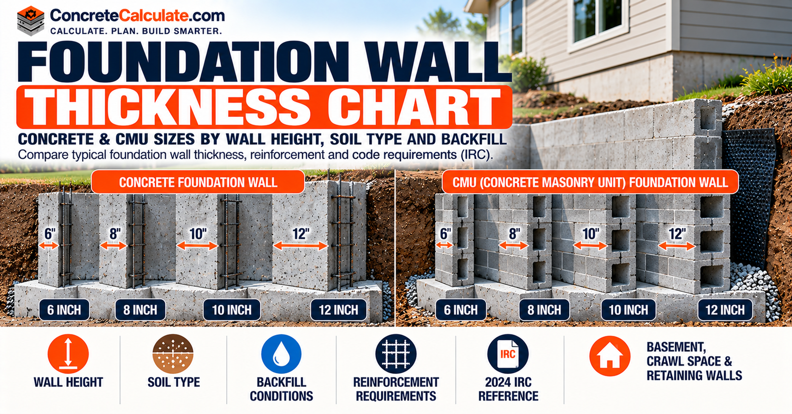
Foundation Wall Thickness Chart
Concrete & CMU Requirements
Foundation wall thickness by material, wall height, unbalanced backfill, soil pressure, reinforcement, and applicable 2024 IRC foundation-wall provisions.
 Reviewed by Muhammad Ramzan Babar, PhD Researcher (Plasma Physics) & Calculator Developer, View Profile
The IRC does not prescribe one universal foundation-wall thickness
Concrete and masonry provisions use separate tables, and increasing backfill height or changing soil conditions can require additional thickness, reinforcement, or engineered design. Do not use a generic “wall thickness by basement height” chart without retaining the wall-height, backfill, soil, reinforcement, and support conditions on which its values depend.
Foundation Wall Thickness Chart, Quick Reference
Thickness categories addressed by applicable foundation-wall provisions, not interchangeable minimums.
| Foundation Wall | Nominal Thickness | Material | Main Design Conditions |
|---|---|---|---|
| Cast-in-place concrete | 6 in | Concrete | Wall height, backfill, soil, reinforcement, seismic limits |
| Cast-in-place concrete | 8 in | Concrete | Wall height, backfill, soil, reinforcement |
| Cast-in-place concrete | 10 in | Concrete | Wall height, backfill, soil, reinforcement |
| Cast-in-place concrete | 12 in | Concrete | Wall height, backfill, soil, reinforcement |
| Masonry | 6-12 in, where permitted | CMU or solid masonry | Unit type, wall height, backfill, soil, reinforcement |
| Insulated concrete forms | System-specific | Concrete core | Approved system and structural design |
Important Code Qualification
Prescriptive tables apply only within their stated conditions. Local adoption, engineering requirements, and every applicable table footnote must be checked before selecting a wall thickness.
Concrete Foundation Wall Thickness Quick Chart
| Nominal Wall Thickness | Required Design Inputs | Applicable IRC Reference |
|---|---|---|
| 6 in | Unsupported wall height, unbalanced backfill, soil load, reinforcement, seismic/support conditions | R404.1.3 tables |
| 8 in | Unsupported wall height, unbalanced backfill, soil load, vertical and horizontal reinforcement | R404.1.3 tables |
| 10 in | Same inputs, plus higher retained-soil and structural demands | R404.1.3 tables |
| 12 in | Same inputs, plus conditions outside thinner-wall scope | R404.1.3 tables / engineering |
Masonry Foundation Wall Thickness Quick Chart
| Wall System | Key Selection Conditions | Applicable IRC Reference |
|---|---|---|
| Plain solid masonry | Wall height, unbalanced backfill, soil load, supported wall | R404.1.2.1(1) |
| Hollow ungrouted CMU | Unit configuration and limited plain-masonry conditions | R404.1.2.1(1) |
| Grouted CMU | Grout, reinforcement, wall height, soil load | R404.1.2.1(2)-(4) |
| Reinforced masonry | Bar size, spacing, grouted cells, backfill, soil | R404.1.2.1(2)-(4) |
Planning your next concrete project?
Plan concrete materials and project costs with our downloadable Excel estimator pack. For estimating only; follow applicable technical standards for design and installation.
One-time purchase · Digital downloadWhat Is Foundation Wall Thickness?
The horizontal structural dimension between wall faces.
Foundation wall thickness is the horizontal dimension between the structural wall faces. This may mean the cast-in-place concrete thickness, nominal CMU thickness, actual CMU unit width, or structural concrete-core thickness in an ICF system. Finished thickness including insulation, membranes, waterproofing, or interior finishes is not necessarily the structural dimension used in engineering calculations.
Foundation Wall Thickness vs Footing Thickness
The vertical wall and the footing beneath it serve different structural functions.
| Component | Primary Structural Function | Thickness Measurement | Main Loading Conditions |
|---|---|---|---|
| Foundation wall | Resists lateral soil pressure and supports wall loads | Horizontal wall dimension | Earth pressure, water, vertical wall load |
| Footing | Spreads loads to the soil | Vertical concrete thickness | Vertical bearing, bending, shear |
See the Footing Size Chart for footing width and thickness; this page focuses on the vertical foundation wall above the footing.
Minimum Foundation Wall Thickness Under the 2024 IRC
The principal code-introduction section.
IRC R404.1 addresses concrete and masonry foundation walls. R404.1.2 covers masonry foundation-wall design, R404.1.3 covers concrete foundation-wall design, R404.1.4 addresses additional seismic requirements, and R404.1.5 addresses thickness based on supported walls. The 2024 IRC does not establish one minimum thickness suitable for every basement or foundation wall; applicable thickness comes from the relevant material-specific table and conditions.
✓ Verified Against 2024 IRC Section R404.1Foundation Wall Thickness Based on the Supported Wall
Thickness also depends on what the foundation wall carries above.
For concrete walls, IRC R404.1.5.2 requires the foundation wall to be at least as thick as the wall in the story above. Masonry has a corresponding provision with specific brick-veneer and cavity-wall exceptions. This supported-wall thickness requirement must be evaluated alongside lateral earth-pressure design; meeting one requirement does not automatically satisfy the other.
Nominal vs Actual Foundation Wall Thickness
Inch and metric conversion reference.
| Nominal Thickness | Equivalent Metric Thickness |
|---|---|
| 6 in | 152.4 mm |
| 8 in | 203.2 mm |
| 10 in | 254.0 mm |
| 12 in | 304.8 mm |
Nominal CMU sizes should not be presented as exact physical measurements. Form tolerances and actual concrete-core dimensions also need separate verification for the specific wall system used.
Poured Concrete Foundation Wall Thickness Chart
A flagship section that preserves the exact table inputs needed for IRC use.
| Nominal Concrete Thickness | Maximum Unsupported Wall Height | Unbalanced Backfill Height | Soil Classification / Lateral Load | Minimum Vertical Reinforcement | IRC Table |
|---|---|---|---|---|---|
| 6 in | Must use row-specific value | Must use row-specific value | 30 / 45 / 60 psf per ft | NR or specified by row | R404.1.3 tables |
| 8 in | Must use row-specific value | Must use row-specific value | 30 / 45 / 60 psf per ft | NR or specified by row | R404.1.3 tables |
| 10 in | Must use row-specific value | Must use row-specific value | 30 / 45 / 60 psf per ft | Specified by row | R404.1.3 tables |
| 12 in | Must use row-specific value | Must use row-specific value | 30 / 45 / 60 psf per ft | Specified by row / engineering | R404.1.3 tables |
Why This Is Not a Universal Thickness-by-Height Table
The 2024 IRC’s concrete basement-wall tables must be used with exact row conditions for unsupported height, unbalanced backfill, soil pressure, vertical reinforcement, lateral supports, and table footnotes. Interpolating between rows or stripping away these conditions produces an unsafe and misleading chart.
Six-Inch Concrete Foundation Wall Requirements
Permitted only within qualifying prescriptive conditions.
Six-inch concrete walls appear within limited IRC prescriptive conditions. Unsupported wall height, unbalanced backfill, lateral soil loads, reinforcement requirements, seismic limitations, and supported-wall thickness all control whether a 6-in wall is permitted. Do not imply a 6-in wall is appropriate for all shallow foundations, crawl spaces, or basement conditions simply because it exists as a table category.
Eight-Inch Concrete Foundation Wall Requirements
The most commonly encountered residential wall category, but still not a universal answer.
The IRC’s dedicated 8-in nominal flat-wall table shows that some qualifying combinations do not require prescriptive vertical reinforcement, while greater backfill height and soil pressure can require specific bar sizes and spacing. A table entry indicating no required vertical reinforcement does not eliminate horizontal reinforcement or other applicable requirements, including seismic and supported-wall provisions.
Ten-Inch and Twelve-Inch Concrete Foundation Walls
Related thicknesses that accommodate particular structural and retained-soil conditions.
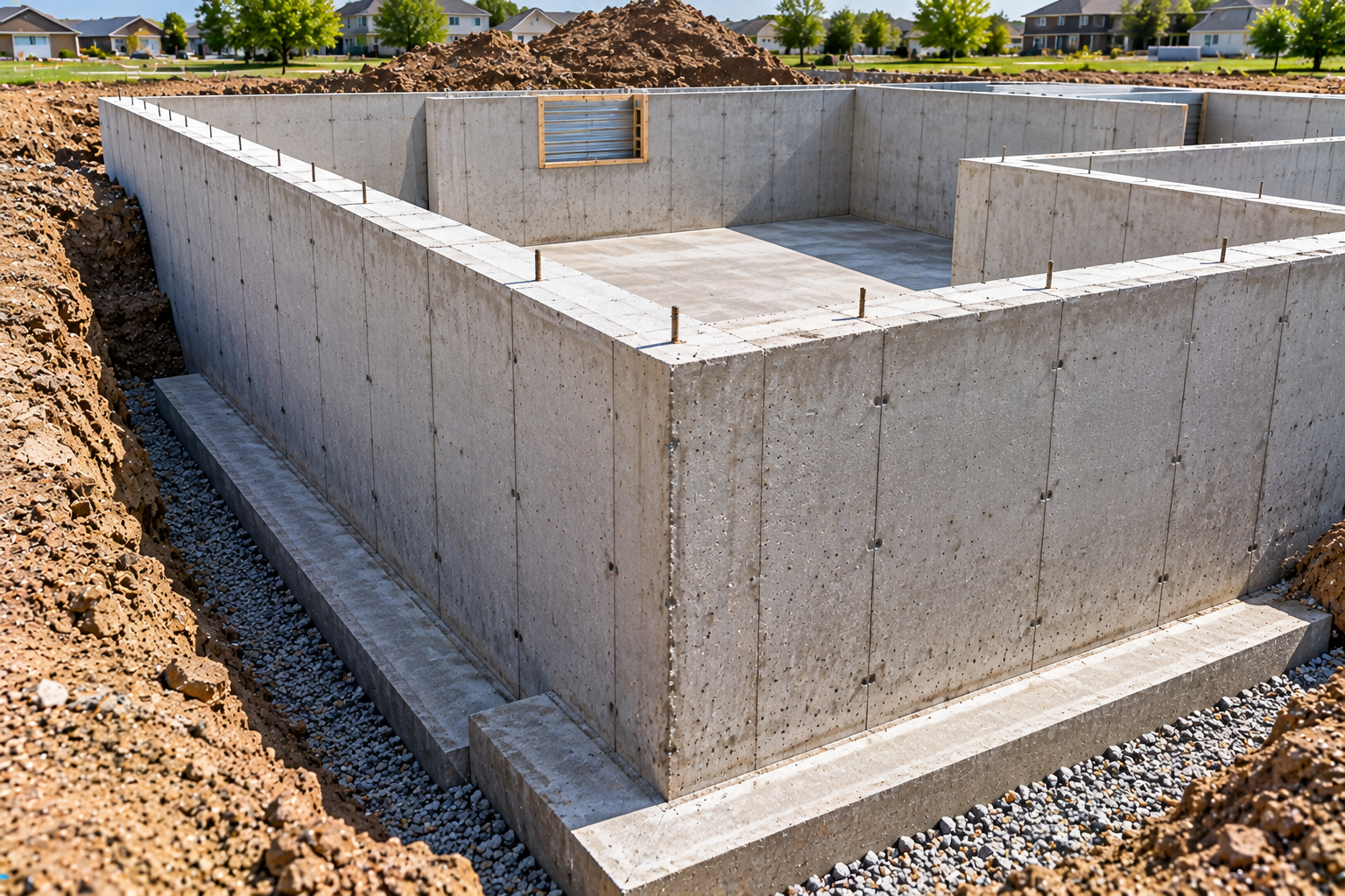
Ten- and twelve-inch concrete walls provide increased wall cross-section for particular retained-soil and structural conditions. Their selection still depends on the applicable code-table limits, reinforcement requirements, construction and concrete-volume implications, and any conditions requiring engineered design. Increasing thickness alone does not always eliminate the need for reinforcement.
Plain vs Reinforced Concrete Foundation Walls
Two different structural systems with different prescriptive limits.
| Feature | Plain Concrete | Reinforced Concrete |
|---|---|---|
| Steel reinforcement | None for structural resistance | Designed reinforcement |
| Flexural behavior | Limited tensile resistance | Reinforcement resists tension |
| Applicable use | Restricted prescriptive conditions | Prescriptive or engineered |
| Wall thickness | Code/design dependent | Code/design dependent |
Minimum reinforcement required by seismic provisions is distinct from reinforcement selected to resist lateral soil pressure. Both must be evaluated under the applicable IRC requirements.
CMU Foundation Wall Thickness Chart
The IRC uses separate foundation-wall tables for masonry systems.
| Nominal Wall Thickness | Unit Configuration | Required Design Inputs | Applicable IRC Table |
|---|---|---|---|
| 6 in | Solid masonry only where permitted | Unsupported height, backfill, soil load, supported wall | R404.1.2.1(1) |
| 8 in | Solid or hollow masonry depending on system | Wall height, backfill, soil, grout/reinforcement | R404.1.2.1(1)-(4) |
| 10 in | Reinforced/grouted masonry as applicable | Wall height, backfill, soil, reinforcement | R404.1.2.1(2)-(4) |
| 12 in | Reinforced/grouted masonry as applicable | Higher demands, backfill, soil, supported walls | R404.1.2.1(2)-(4) |
The IRC distinguishes plain masonry, solid masonry units, hollow ungrouted CMU, grouted CMU, and reinforced masonry. Use Table R404.1.2.1(1) for qualifying plain masonry and Tables R404.1.2.1(2)-(4) for applicable reinforced masonry systems.
✓ Verified Against 2024 IRC R404.1.2 FrameworkSix-Inch vs Eight-Inch CMU Foundation Walls
An important distinction between solid and hollow masonry.
The 2024 IRC plain masonry table permits some 6-in solid or 8-in nominal alternatives for specified wall-height, backfill, and soil conditions. That does not make every hollow 6-in block equivalent to a solid 6-in masonry unit. The actual unit configuration and the table’s exact permitted conditions must be verified before selection.
See the Masonry Block Size Chart for nominal and actual CMU dimensions.
Ten-Inch and Twelve-Inch CMU Foundation Walls
Larger masonry configurations for greater demand conditions.
Larger masonry foundation-wall configurations interact with backfill height, soil pressure, grouting, vertical reinforcement, supported-wall loads, and prescriptive table limits. Where plain masonry is outside its permitted scope, transition to a properly designed reinforced masonry assembly or engineered design rather than assuming greater nominal block width alone resolves every condition.
Grouted vs Ungrouted CMU Foundation Walls
Different systems, not a field modification made without a design basis.
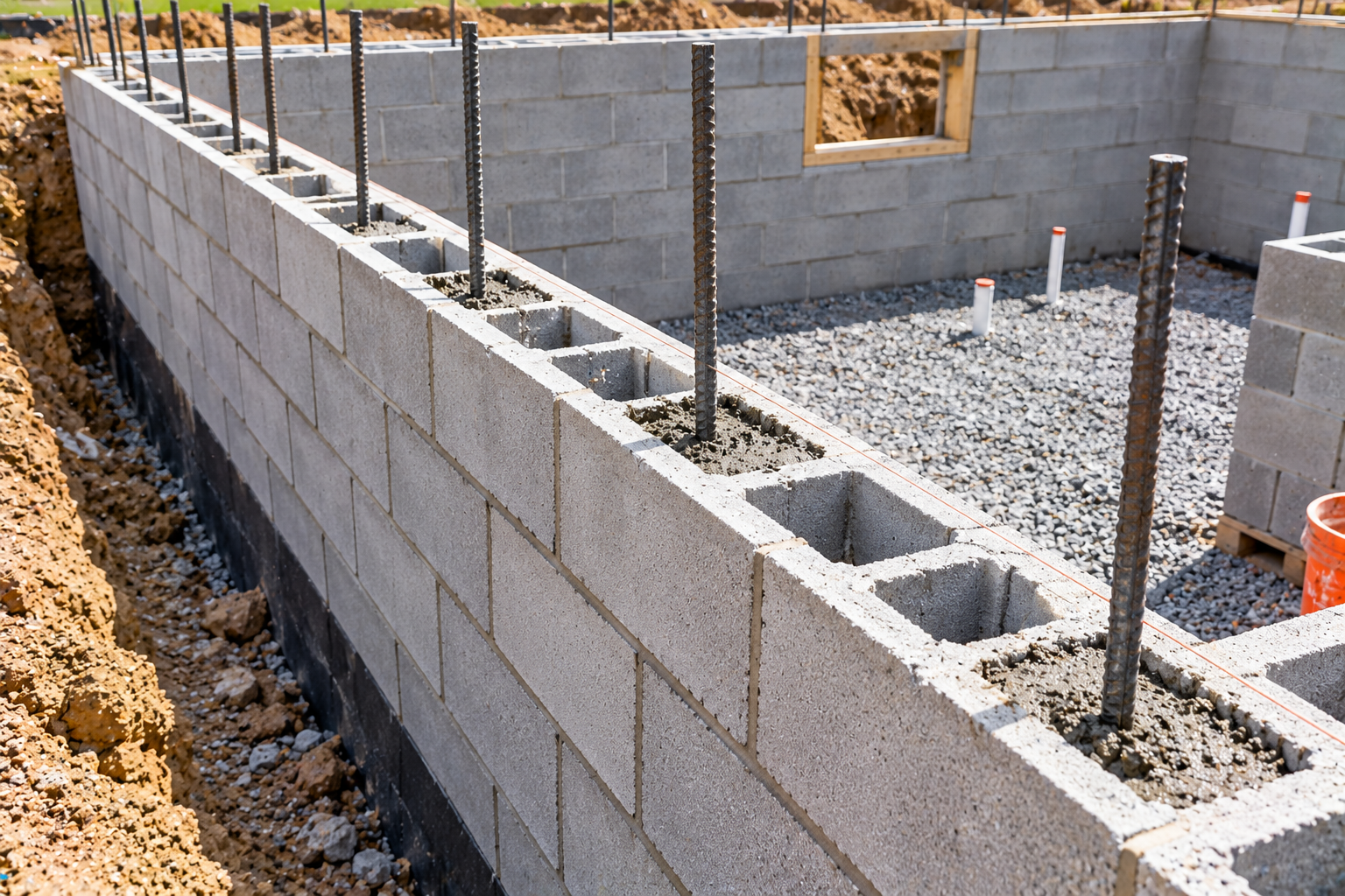
Hollow CMU contains cells that may remain ungrouted or be grouted and reinforced. Grouted reinforced masonry involves specified reinforced cells, bar placement, grout continuity, and bond beams where required. Grout and reinforcement must follow an approved assembly or design rather than being added arbitrarily to an unsuitable wall configuration.
ICF and Specialty Foundation Wall Thickness
Structural core thickness, not total form thickness, controls the design.
Insulated concrete forms and specialty wall systems require separate consideration of overall form thickness and structural concrete-core thickness. Flat concrete cores, waffle-grid systems, and screen-grid systems have different structural behavior. Manufacturer documentation, approved system evaluation, and applicable IRC R608 provisions govern their use; do not simply treat total foam-plus-concrete form thickness as equivalent to a solid cast-in-place wall of the same overall width.
Unsupported Foundation Wall Height vs Thickness
A key measurement that is not interchangeable with total wall height.
| Term | Meaning |
|---|---|
| Total wall height | Overall height of the foundation wall |
| Unsupported wall height | Code-defined wall height without permanent lateral support at top/bottom |
| Retained-soil height | Exterior soil height acting laterally against the wall |
| Height above grade | Portion of wall exposed above exterior finish grade |
Greater unsupported wall height increases wall-bending demand. Do not treat total wall height, unsupported wall height, retained-soil height, and unbalanced backfill as interchangeable values.
Unbalanced Backfill Height Chart
One of the strongest standalone technical sections in this article.
For qualifying conditions, the IRC permits unbalanced backfill measurement from exterior finished grade to the top of an interior slab in contact with the foundation wall. Otherwise, the reference depends on the lower of the top of the supporting footing or interior finished grade. This measurement directly affects which foundation-wall table row applies.
| Wall Height | Unbalanced Backfill | Soil Load Categories | Relevant Wall Table |
|---|---|---|---|
| 6 ft | 4 ft | 30 / 45 / 60 psf per ft | Applicable concrete or masonry table |
| 7 ft | 5 ft | 30 / 45 / 60 psf per ft | Applicable concrete or masonry table |
| 8 ft | 6 ft | 30 / 45 / 60 psf per ft | Applicable concrete or masonry table |
| 9 ft | 8 ft | 30 / 45 / 60 psf per ft | Applicable table or engineered design |
Navigation Chart Only
This chart does not assert that every listed combination is permitted for every thickness. Select the exact applicable concrete or masonry table and preserve every condition and footnote.
Equipment for Your Project
Affiliate disclosure: As an Amazon Associate, ConcreteCalculate earns from qualifying purchases. We may also earn a commission from other affiliate links at no additional cost to you.
How Soil Type Affects Foundation Wall Thickness
The IRC lateral soil categories are different from vertical bearing capacity.
| Soil Group | Representative Lateral Load |
|---|---|
| GW, GP, SW, SP | 30 psf per foot |
| GM, GC, SM, SM-SC, ML | 45 psf per foot |
| SC, ML-CL, inorganic CL | 60 psf per foot |
These values apply in the context of the specified IRC foundation-wall tables, not as universal values for every retaining structure. Lateral soil pressure is distinct from vertical soil-bearing capacity; see the Soil Bearing Capacity Chart for the latter.
✓ Verified Against 2024 IRC R404 Soil Classification FrameworkLateral Earth Pressure and Surcharge Loads
Why foundation walls must resist horizontal pressure from retained soil.
Foundation walls resist lateral earth pressure that generally increases with depth. Additional factors include surcharge from vehicles or nearby structures, sloping backfill, compaction pressure, wall movement conditions, and lateral supports. A conceptual triangular soil-pressure distribution can be useful for simple cases, but actual design pressures depend on site and structural conditions, so a generic wall-thickness chart cannot replace appropriate engineering for unusual retained-soil conditions.
Hydrostatic Pressure and Groundwater
Water pressure is not solved by simply increasing wall thickness.
The IRC requires engineered design where a foundation wall is subject to hydrostatic pressure from groundwater. Hydrostatic loading, perimeter drainage, waterproofing, groundwater elevation, drainage failure, and combined water-and-soil pressure must all be considered. Do not suggest that increasing wall thickness alone resolves a groundwater problem.
✓ Verified Against 2024 IRC R404.1.1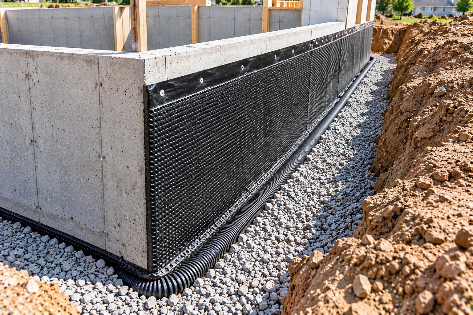
Above-Grade Loads and Supported Wall Types
What the structure above contributes to wall selection.
Light-frame walls, masonry walls, concrete walls, masonry veneer, concentrated structural loads, and wall alignment all affect foundation-wall selection. Wall thickness must satisfy both retained-soil loading and the applicable requirements for the wall being supported above, including the IRC supported-wall thickness provisions.
Foundation Wall Vertical Reinforcement Chart
How to read the exact applicable IRC provisions without inventing a universal schedule.
| Wall System | Nominal Thickness | Required Inputs | Vertical Reinforcement Result | Code Reference |
|---|---|---|---|---|
| Flat concrete | 6 / 8 / 10 / 12 in | Unsupported height, backfill, soil category, support condition | NR or bar size/spacing per exact row | R404.1.3 tables |
| Plain masonry | 6-12 in where allowed | Unit configuration, height, backfill, soil | Plain masonry conditions only | R404.1.2.1(1) |
| Reinforced masonry | 8 / 10 / 12 in | Height, backfill, soil, grout/reinforcement configuration | Bar size/spacing per exact row | R404.1.2.1(2)-(4) |
Definitions
NR means vertical reinforcement is not required under the specified prescriptive table conditions. DR means engineered design is required. Do not interpolate between table rows where the code prohibits interpolation, and do not use a row without matching all of its stated inputs and footnotes.
Horizontal Reinforcement Requirements
Separate from the vertical reinforcement selected for lateral soil pressure.
Horizontal reinforcing bars, bar locations, continuous reinforcement, wall intersections, construction joints, and seismic requirements depend on the specified wall type and the applicable IRC tables and supplemental provisions. Do not assume all concrete and masonry walls have identical horizontal reinforcement requirements, even when their nominal thickness is the same.
Concrete Cover and Rebar Placement
Thickness alone does not establish correct reinforcement placement.
Correct reinforcement placement includes clear concrete cover, interior and exterior faces, vertical and horizontal bar locations, minimum spacing, bar supports, and placement accuracy. See the Concrete Cover Chart, Rebar Spacing Chart, and Rebar Size Chart for the associated reinforcement references.
Foundation Wall Thickness in Seismic Areas
Specialized provisions that should not be applied everywhere.
IRC provisions for Seismic Design Categories D0, D1, and D2 impose additional foundation-wall requirements. For example, the 2024 IRC’s additional plain masonry requirements include an 8-in nominal minimum under stated conditions, plus limits on wall and unbalanced-backfill heights. Concrete provisions separately address plain-wall thickness and minimum seismic reinforcement. Do not apply these specialized provisions to every U.S. jurisdiction without first confirming the project’s applicable seismic design category.
Engineered Foundation Wall Design
When prescriptive tables are insufficient.
Engineered design is appropriate when the project falls outside the applicable prescriptive conditions. Relevant design approaches include ACI 318 for structural concrete, ACI 332 or other permitted residential concrete provisions where applicable, TMS 402 for masonry design, and the locally adopted building code. Typical engineering checks include bending, shear, axial loading, reinforcement, deflection, and combined loading. Wall thickness cannot be selected from a generic chart when the project falls outside the applicable prescriptive conditions.
Openings, Corners, and Construction Joints
Discontinuities that often require special detailing.
Basement windows, door openings, service penetrations, wall intersections, corners, construction joints, and concentrated loads all create discontinuities that may require special reinforcement or detailing. This general chart does not provide a reinforcement design for those conditions; project-specific drawings or engineering should address them.
Basement vs Crawl-Space vs Stem Wall Thickness
Foundation type changes the wall condition, not a universal thickness number.
| Foundation Type | Main Wall Condition | Thickness-Selection Factors |
|---|---|---|
| Basement | Significant retained soil may be present | Backfill, soil, water, wall height |
| Crawl space | Often shorter, but site dependent | Retained soil, height, supported wall |
| Stem wall | Transfers building loads to footings | Supported wall and lateral loads |
| Slab perimeter | May have thickened edge or stem wall | Design and code provisions |
Do not assign a universal thickness to any foundation type without checking the actual wall, soil, and loading conditions.
Foundation Wall Thickness and Footing Connection
How the vertical wall connects to its supporting footing.
Wall alignment over the footing, footing width, bearing and load transfer, wall-to-footing connection, reinforcement continuity, dowels where required, and foundation anchorage all influence the overall foundation assembly. Keep the footing’s detailed sizing on the Footing Size Chart and related Anchor Bolt Spacing Chart.
Foundation Wall Thickness and Concrete Quantity
A practical concrete-volume chart for 10-ft wall segments.
Formula
V = L × H × t, where all dimensions use consistent units. Convert cubic feet to cubic yards by dividing by 27.
| Wall Height | 6-in Wall | 8-in Wall | 10-in Wall | 12-in Wall |
|---|---|---|---|---|
| 4 ft | 0.74 yd³ | 0.99 yd³ | 1.23 yd³ | 1.48 yd³ |
| 6 ft | 1.11 yd³ | 1.48 yd³ | 1.85 yd³ | 2.22 yd³ |
| 8 ft | 1.48 yd³ | 1.98 yd³ | 2.47 yd³ | 2.96 yd³ |
Theoretical concrete volume for a 10-ft-long wall before openings and waste. Subtract openings, account for thickened elements, and calculate footings separately. See the Foundation Wall Calculator and Concrete Foundation Calculator for project-specific volume calculations.
✓ Verified: Volumes Calculated Directly From L x H x tHow to Choose and Verify Foundation Wall Thickness
A practical selection process that preserves the code-table logic.
Foundation Wall Selection Workflow
Common Foundation Wall Thickness Mistakes
Assuming every residential basement needs an 8-in wall
Wall height, backfill, soil, reinforcement, and supported-wall conditions all matter.
Treating an 8-in wall as sufficient regardless of backfill
Greater unbalanced backfill can require different reinforcement, thickness, or engineering.
Confusing foundation-wall thickness with footing thickness
These dimensions describe different components and loading functions.
Using total wall height instead of unsupported wall height
The code-table measurement must match the table definition exactly.
Measuring unbalanced backfill incorrectly
This height is defined by specific exterior and interior reference elevations.
Confusing vertical soil bearing with lateral soil pressure
They are separate soil properties affecting different parts of foundation design.
Ignoring groundwater and hydrostatic pressure
Hydrostatic conditions require engineering rather than a simple thickness increase.
Applying plain-masonry tables to reinforced masonry
These systems have different design conditions and tables.
Treating hollow 6-in masonry as equivalent to solid 6-in masonry
Unit configuration is a key condition in the masonry table.
Using reinforcement requirements from the wrong wall system
Concrete, plain masonry, and reinforced masonry have separate requirements.
Assuming no vertical reinforcement in one table means none anywhere
Other horizontal, seismic, and local provisions may still apply.
Overlooking seismic provisions
D0, D1, and D2 conditions can add special foundation-wall requirements.
Ignoring lateral support requirements
Permanent top and bottom support affects whether prescriptive provisions apply.
Backfilling too early
Walls need sufficient strength and required anchorage or bracing before major backfill.
Increasing thickness without checking other structural requirements
Thickness alone does not replace reinforcement, drainage, or engineering.
Treating ICF form thickness as concrete-core thickness
Structural design is based on the actual concrete core and system configuration.
Using a generic chart for engineered retaining walls
Retaining walls beyond prescriptive scope require project-specific design.
Ignoring local code amendments
The adopted jurisdiction can amend the model IRC provisions.
Foundation Wall Thickness Chart Limitations
Read Before Foundation Wall Selection or Construction
Prescriptive IRC tables apply only within their stated building types and conditions. Local amendments, geotechnical findings, groundwater, slopes, adjacent structures, seismic design category, unusual loads, and engineered designs can supersede simplified reference values. This page does not reproduce code table rows without their complete conditions because stripping wall height, backfill, soil pressure, reinforcement, support, and footnote requirements from the table would be unsafe. Confirm the locally adopted code, exact table row, material system, and approved construction plans before choosing foundation wall thickness or reinforcement.
Frequently Asked Questions
Download Foundation Wall Thickness Chart PDF
Save or print this reference including the concrete and CMU wall selection tables, lateral soil-load categories, concrete quantity chart, and foundation-wall verification workflow.