Steel I-Beam Chart 2026 – W-Shapes, Weights & Properties
Steel I-Beam Chart
W-Shapes, Weights & Properties
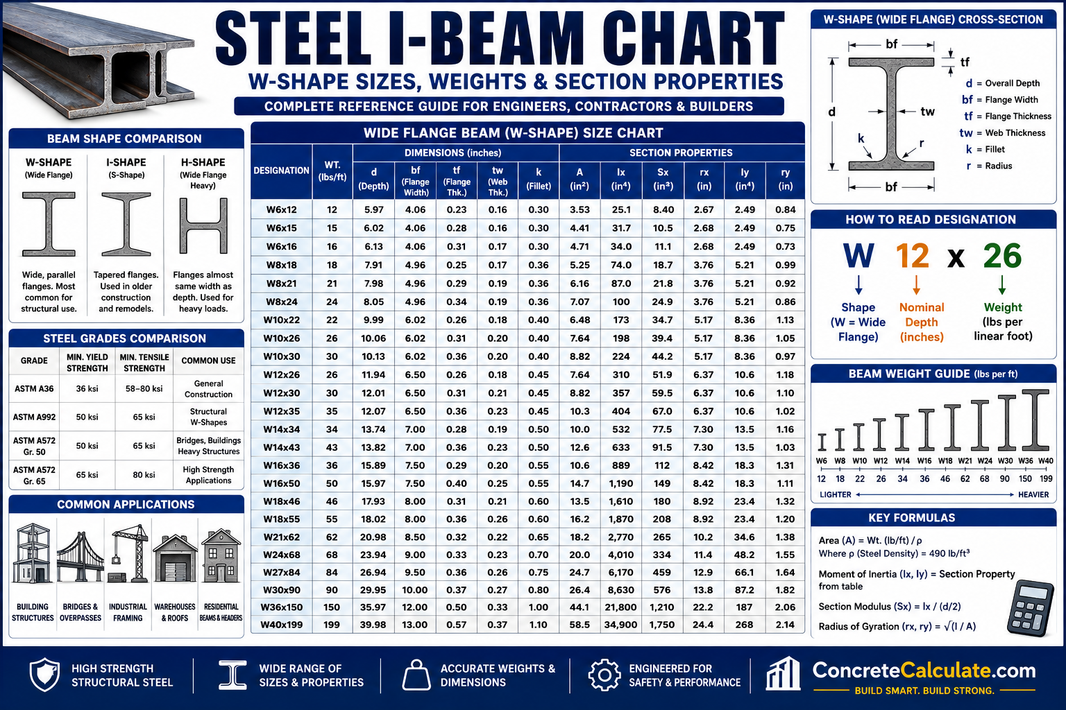
Complete steel beam reference for engineers and contractors — W-shape dimensions, weights, section properties, grades, and structural applications.
 Reviewed by Muhammad Ramzan Babar, PhD Researcher (Plasma Physics) & Calculator Developer — View Profile
Important: Engineering Reference Only
This page summarizes commonly used W-shapes and general engineering concepts for planning purposes. It is not a substitute for the AISC Steel Construction Manual or a licensed structural engineer’s design — final beam selection must always be verified through proper structural calculation.
⭐ Master Steel I-Beam Chart
Complete overview of standard steel W-shape sizes, dimensions, weights, section properties, and structural applications.
How to Read This Chart
Rather than reproducing the full AISC Steel Construction Manual, this page summarizes the most commonly specified W-shapes by depth series and explains what each dimension and property means in practical terms. For load-specific sizing, verify with our Concrete Beam Calculator and Load Bearing Calculator.
| Series | Typical Depth | Typical Weight Range | Common Use Category |
|---|---|---|---|
| W4–W6 | 4″–6″ | 7–25 lb/ft | Light residential, small headers |
| W8–W10 | 8″–10″ | 15–68 lb/ft | Garage/basement beams, light commercial |
| W12–W14 | 12″–14″ | 14–800+ lb/ft | Commercial floors, columns, wide range of use |
| W16–W18 | 16″–18″ | 26–311 lb/ft | Longer commercial and warehouse spans |
| W21–W24 | 21″–24″ | 44–408 lb/ft | Larger commercial and industrial spans |
| W27–W30 | 27″–30″ | 84–436 lb/ft | Long-span industrial and bridge-adjacent use |
| W36–W40 | 36″–40″ | 135–655 lb/ft | Heavy industrial, bridges, long-span roofs |
⭐ Standard Steel I-Beam Size Chart
Representative W-shapes from each common depth series, summarizing depth, flange width, and weight per foot for quick comparison.
| Beam Designation | Depth (d) | Flange Width (bf) | Weight/ft | Weight/m |
|---|---|---|---|---|
| W4×13 | 4.16″ | 4.06″ | 13 lb | 19.3 kg |
| W6×9 | 5.90″ | 3.94″ | 9 lb | 13.4 kg |
| W8×18 | 8.14″ | 5.25″ | 18 lb | 26.8 kg |
| W10×22 | 10.17″ | 5.75″ | 22 lb | 32.7 kg |
| W12×26 | 12.22″ | 6.49″ | 26 lb | 38.7 kg |
| W14×30 | 13.84″ | 6.73″ | 30 lb | 44.6 kg |
| W16×36 | 15.86″ | 6.99″ | 36 lb | 53.6 kg |
| W18×50 | 17.99″ | 7.50″ | 50 lb | 74.4 kg |
| W21×62 | 20.99″ | 8.24″ | 62 lb | 92.3 kg |
| W24×76 | 23.92″ | 8.99″ | 76 lb | 113.1 kg |
| W27×94 | 26.92″ | 9.99″ | 94 lb | 139.9 kg |
| W30×99 | 29.65″ | 10.45″ | 99 lb | 147.3 kg |
| W36×135 | 35.55″ | 11.95″ | 135 lb | 200.9 kg |
| W40×167 | 39.99″ | 11.98″ | 167 lb | 248.4 kg |
One Representative Shape Per Series
Each depth series (W12, W14, W18, etc.) contains many different weight options — for example, W12 shapes range from lightweight W12×14 up to heavy W12×336 columns. This chart shows one common representative shape per series; the full AISC Manual should be consulted for the complete shape list.
⭐ Steel I-Beam Dimensions Chart
Understanding each geometric dimension that defines a W-shape cross-section.
| Dimension | Symbol | What It Means |
|---|---|---|
| Overall Depth | d | Total height of the beam from top flange to bottom flange |
| Flange Width | bf | Width of the horizontal top and bottom flange plates |
| Web Thickness | tw | Thickness of the vertical plate connecting the two flanges |
| Flange Thickness | tf | Thickness of each horizontal flange plate |
| Root Radius / Fillet Radius | k or r | Curved transition where the web meets the inside face of the flange, reducing stress concentration |
Note that the nominal depth in a designation (e.g., the “12” in W12×26) is a rounded label, not the exact physical depth — the actual depth of a W12×26 is 12.22 inches.
⭐ Steel I-Beam Weight Chart
One of the most searched steel beam topics — weight per foot, per meter, and typical total weight for common lengths.
| Beam Size | Weight per Foot | Weight per Meter | Weight per 20-ft Beam |
|---|---|---|---|
| W6×9 | 9 lb | 13.4 kg | 180 lb |
| W8×18 | 18 lb | 26.8 kg | 360 lb |
| W10×22 | 22 lb | 32.7 kg | 440 lb |
| W12×26 | 26 lb | 38.7 kg | 520 lb |
| W14×30 | 30 lb | 44.6 kg | 600 lb |
| W18×50 | 50 lb | 74.4 kg | 1,000 lb |
| W24×76 | 76 lb | 113.1 kg | 1,520 lb |
Total beam weight scales directly with length — a W12×26 at 20 feet weighs 520 lb, while the same shape at 30 feet weighs 780 lb (26 lb/ft × length).
Steel I-Beam Section Properties Chart
Key geometric properties that engineers use to calculate bending and deflection capacity.
| Beam Size | Area (in²) | Ix (in⁴) | Iy (in⁴) | Sx (in³) | rx (in) | ry (in) |
|---|---|---|---|---|---|---|
| W8×18 | 5.26 | 61.9 | 7.97 | 15.2 | 3.43 | 1.23 |
| W10×22 | 6.49 | 118 | 11.4 | 23.2 | 4.27 | 1.33 |
| W12×26 | 7.65 | 204 | 17.3 | 33.4 | 5.17 | 1.51 |
| W14×30 | 8.85 | 291 | 19.6 | 42.0 | 5.73 | 1.49 |
| W16×36 | 10.6 | 448 | 24.5 | 56.5 | 6.51 | 1.52 |
| W18×50 | 14.7 | 800 | 40.1 | 88.9 | 7.38 | 1.65 |
| Property | What It Tells You |
|---|---|
| Cross-Sectional Area | Total steel area in the cross-section; relates to weight and axial capacity |
| Moment of Inertia (Ix) | Resistance to bending about the strong axis; higher Ix means a stiffer beam |
| Moment of Inertia (Iy) | Resistance to bending about the weak axis, relevant for lateral stability |
| Section Modulus (Sx) | Relates bending moment to maximum bending stress; used to check beam strength |
| Radius of Gyration (rx, ry) | Measures how efficiently the cross-section resists buckling in each direction |
These section properties are essential inputs for engineered beam design but should always be paired with proper load calculations — see our Load Bearing Calculator.
⭐ Steel I-Beam by Construction Application
Matching beam series to common project categories based on typical load and span demands.
| Project | Recommended Beam Series |
|---|---|
| Residential Houses | W6–W10 |
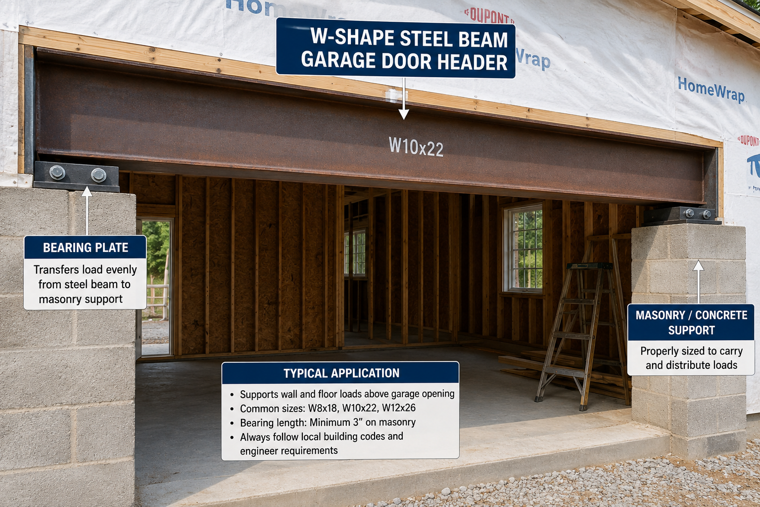
| Garages | W6–W8 |
| Deck Supports | W6–W8 |
| Floor Framing | W8–W12 |
| Commercial Buildings | W12–W21 |
| Warehouses | W16–W27 |
| Industrial Structures | W21–W36 |
| Bridges | W27–W40 or plate girders |
| Crane Beams | W18–W30, often reinforced |
Wide Flange (W-Beam) Chart
Understanding the standard AISC naming convention for W-shapes.
| Designation Part | Example (W12×26) | What It Means |
|---|---|---|
| Shape Letter | W | Identifies the shape family — wide flange |
| First Number | 12 | Nominal depth in inches (rounded label, not exact) |
| Second Number | 26 | Weight per linear foot in pounds |
Why This Matters
Two beams in the same “W12” family can have very different actual depths and flange widths depending on weight — a W12×14 is much lighter and shallower than a W12×336, even though both share the “W12” nominal label. Always check the full designation, not just the depth number.
⭐ I-Beam vs Wide Flange Beam
One of the most searched steel beam comparisons — understanding the practical differences between S-shapes and W-shapes.
| Factor | I-Beam (S-Shape) | Wide Flange (W-Shape) |
|---|---|---|
| Shape | Narrower, tapered flanges | Wider, parallel-faced flanges |
| Flange Geometry | Sloped inner flange surface | Flat, constant-thickness flange |
| Strength | Good for pure bending | Better overall strength-to-weight for combined loads |
| Weight | Generally lighter per depth | Can be optimized lighter or heavier per application |
| Applications | Legacy structures, some industrial use | Modern beams, columns, general structural framing |
| Availability | Limited, fewer sizes produced today | Widely available in extensive size range |
⭐ I-Beam vs H-Beam
Another major search topic — comparing traditional I-beams against H-shaped wide flange sections.
| Factor | I-Beam | H-Beam |
|---|---|---|
| Geometry | Tapered flange, I-shaped profile | Flat flange, H-shaped profile with wider flanges |
| Flange Width | Narrower relative to depth | Wider, often closer to overall depth |
| Web Thickness | Generally thinner | Often thicker for higher shear/axial capacity |
| Structural Capacity | Efficient for bending-dominant loads | Better for combined bending and axial/column loads |
| Typical Uses | Beams, legacy framing | Columns, beams, piles, heavy structural members |
Steel I-Beam Span Guide
Rather than presenting fixed code-based span numbers, here’s how span capability generally scales by application category.
| Application Category | General Span Character |
|---|---|
| Light Residential | Shorter spans, smaller series (W6–W8) typically sufficient |
| Residential Floors | Moderate spans, W8–W12 common depending on load path |
| Commercial Buildings | Longer spans, W12–W21 common for floor and roof framing |
| Warehouses | Long clear spans, W16–W27 to minimize interior columns |
| Industrial Buildings | Longest spans and heaviest loads, W21–W40 or built-up sections |
Spans Are Never One-Size-Fits-All
Actual allowable span depends on beam size, steel grade, applied loading, support conditions (simple span vs cantilever), and deflection criteria — always confirm with an engineered calculation rather than a general chart.
Steel I-Beam Load Considerations
Different load types combine to determine the total design load a beam must safely carry.
| Load Type | Description | Effect on Beam Selection |
|---|---|---|
| Dead Load | Permanent weight of structure and fixed elements | Constant baseline load requirement |
| Live Load | Variable load from occupants, furniture, equipment | Increases required beam capacity for occupied areas |
| Snow Load | Accumulated snow weight on roof structures | Can significantly increase roof beam sizing in cold regions |
| Wind Load | Lateral and uplift forces from wind | Affects bracing and connection design more than beam depth alone |
| Point Loads | Concentrated loads at specific locations | Can require larger beams than an equivalent uniform load |
| Uniform Loads | Evenly distributed load along the beam length | Standard basis for most span/load tables |
Verify total design load with our Slab Load Calculator before finalizing beam selection.
Steel Grades for I-Beams
Comparing common ASTM structural steel specifications used for W-shapes.
| Grade | Yield Strength | Typical Applications | Advantages |
|---|---|---|---|
| ASTM A36 | 36 ksi | Plates, bars, connection elements, older W-shapes | Widely available, cost-effective, ductile |
| ASTM A572 Grade 50 | 50 ksi | High-strength shapes and plates | Higher strength-to-weight than A36 |
| ASTM A992 | 50–65 ksi | Standard modern W-shape beams and columns | Default grade for W-shapes; excellent weldability and ductility |
| ASTM A588 (Weathering Steel) | 50 ksi | Unpainted bridges, exposed structures | Forms a protective oxide layer, reduces maintenance painting |
ASTM A992 is the default specification for modern W-shape beams and columns due to its combination of strength, weldability, and consistent availability.
Steel I-Beam by Building Type
Typical beam series by overall building classification.
| Building Type | Typical Beam Series |
|---|---|
| Houses | W6–W10 |
| Garages | W6–W8 |
| Warehouses | W16–W27 |
| Steel Buildings | W12–W24, often paired with rigid frames |
| Industrial Plants | W21–W36+ |
| Agricultural Buildings | W8–W16, sometimes combined with timber |
| Bridges | W27–W40 or engineered plate girders |
Beam Bearing & Connection Guide
Overview of common methods for transferring load from a steel beam into its supports.
| Connection Type | Description | Common Use |
|---|---|---|
| Bearing Plates | Steel plate distributing beam reaction over masonry/concrete | Beam ends on walls or piers |
| Column Connections | Beam-to-column joints via clips, plates, or direct welding | Multi-story steel frames |
| Bolted Connections | High-strength bolts through connection plates | Field connections, easier erection and future disassembly |
| Welded Connections | Shop or field welds joining beam to supporting member | Rigid connections, moment frames |
| End Plates | Plate welded to beam end, bolted to supporting member | Moment connections at beam-column joints |
| Base Plates | Plate at column base transferring load to foundation | Column-to-foundation connections |
Size base plates and anchor bolts with our Base Plate Calculator and Anchor Bolt Calculator, and verify embedment with the Anchor Bolt Embedment Calculator.
Steel I-Beam Camber Guide
An often-overlooked but practically important beam property.
| Concept | Explanation |
|---|---|
| What Camber Is | A slight upward curve built into a beam before it is loaded |
| Why It’s Used | Compensates for anticipated dead-load deflection so the beam settles level under service load |
| Typical Applications | Long-span floor beams, bridge girders, and beams supporting heavy concrete decks |
Camber is specified in inches over the beam’s length and is built in during fabrication — it is not something added on-site, and it should not be confused with structural defects like sweep or bow.
Steel I-Beam Corrosion Protection
Comparing common approaches to protecting structural steel from corrosion and fire.
| Method | Description | Typical Use |
|---|---|---|
| Painted Steel | Primer plus topcoat paint system | Interior and general exterior applications |
| Galvanized Steel | Zinc coating applied by hot-dip process | Exterior, high-moisture, or corrosive environments |
| Weathering Steel (A588) | Forms a stable protective rust layer | Unpainted bridges, exposed architectural steel |
| Fireproof Coatings | Intumescent paint or sprayed fireproofing | Fire-rated commercial and high-rise structures |
Steel I-Beam vs Timber Beam
Comparing structural steel against timber for common beam applications.
| Factor | Steel I-Beam | Timber Beam |
|---|---|---|
| Strength | Higher strength-to-weight ratio | Lower strength-to-weight, but adequate for many spans |
| Weight | Heavier overall, but efficient per unit strength | Lighter overall for smaller spans |
| Span Capability | Longer spans achievable in same depth | Shorter spans without engineered wood products |
| Fire Performance | Loses strength rapidly at high temperature without fireproofing | Chars predictably, can retain some capacity longer in mass timber |
| Cost | Higher material cost, faster erection | Generally lower material cost for residential-scale work |
| Installation | Requires cranes/rigging for larger sizes | Easier to handle manually at smaller sizes |
For timber-specific sizing, see our Beam Size Chart and Lumber Span Chart.
Steel I-Beam vs Concrete Beam
Comparing steel and reinforced concrete for common structural beam applications.
| Factor | Steel I-Beam | Concrete Beam |
|---|---|---|
| Construction Speed | Fast, prefabricated and bolted/welded in place | Slower, requires formwork and curing time |
| Weight | Lighter per unit strength | Heavier due to concrete mass |
| Structural Capacity | High strength-to-weight, efficient for long spans | High mass and stiffness, good for fire resistance |
| Cost | Higher material cost, lower labor/time cost | Lower material cost, higher labor/formwork cost |
| Maintenance | Requires corrosion protection over time | Generally low maintenance once cured |
| Best Applications | Long spans, fast-track construction, steel-frame buildings | Fire-rated structures, parking garages, foundations |
For concrete beam sizing, see our Concrete Beam Calculator and Concrete PSI Guide.
⭐ Steel I-Beam Selection Guide
Quick decision reference matching project type to recommended beam series with reasoning.
| Project | Recommended Beam Series | Why |
|---|---|---|
| Garage Opening | W6–W8 | Adequate capacity for typical residential garage headers |
| Basement Beam | W8–W10 | Common for supporting residential floor loads above |
| Warehouse | W16–W27 | Long clear spans minimize interior columns |
| Commercial Floor | W12–W18 | Balances span and floor-to-floor height constraints |
| Bridge | W27–W40 or plate girders | Long spans and heavy vehicular loads require deep sections |
| Mezzanine | W10–W16 | Moderate spans with limited headroom impact |
| Industrial Building | W21–W36 | Heavy equipment loads and long spans common in industrial use |
⭐ Visual Steel I-Beam Guide
Original engineering diagrams explaining W-shape geometry, beam profiles, series comparisons, and connection types.
Steel I-Beam Identification Guide
How to interpret a steel beam marking like W18×35 in the field or on drawings.
| Marking Part | Example (W18×35) | Meaning |
|---|---|---|
| W | W | Wide flange shape family |
| 18 | 18 | Nominal depth in inches (actual depth is close but not exact) |
| 35 | 35 | Weight per linear foot in pounds |
Mill markings rolled into the beam web or flange typically include the shape designation, heat number, and grade — always cross-reference the physical marking against shop drawings before installation.
Common Steel Beam Selection Mistakes
Avoiding these errors prevents structural failures, costly rework, and connection problems.
Choosing by Depth Only
Selecting a beam based solely on nominal depth ignores weight, flange width, and section properties that actually determine capacity.
Ignoring Beam Weight
Heavier structural loads or long spans require checking weight per foot, not just depth, to confirm adequate strength.
Overlooking Deflection
A beam strong enough to avoid failure may still deflect excessively, cracking finishes or feeling unstable.
Using the Wrong Steel Grade
Substituting A36 for A992 (or vice versa) without checking yield strength assumptions can invalidate a structural design.
Incorrect Bearing Length
Insufficient bearing at beam ends can lead to web crippling or crushing of the support material.
Poor Connection Detailing
Under-designed bolted or welded connections can become the weak point of an otherwise adequate beam.
Not Considering Lateral Bracing
Long unbraced beam lengths can fail by lateral-torsional buckling well before reaching their full bending capacity.
Assuming All W-Beams Have the Same Flange Width
Flange width varies significantly by weight within the same depth series, affecting stability and connection design.
Contractor Worked Examples
Real-world steel beam selection scenarios for common project types. Pair these with our Load Bearing Calculator and Bearing Pressure Calculator.
Garage Door Opening
Warehouse Beam
Frequently Asked Questions
📄 Download Steel I-Beam Chart PDF
Get a professional printable engineering reference including W-beam size tables, weight tables, section property tables, steel grade comparison, connection details, cross-section diagrams, beam designation guide, and field-ready reference sheet.