Roof Truss Span Chart – Types, Loads, Spacing & Design Guide
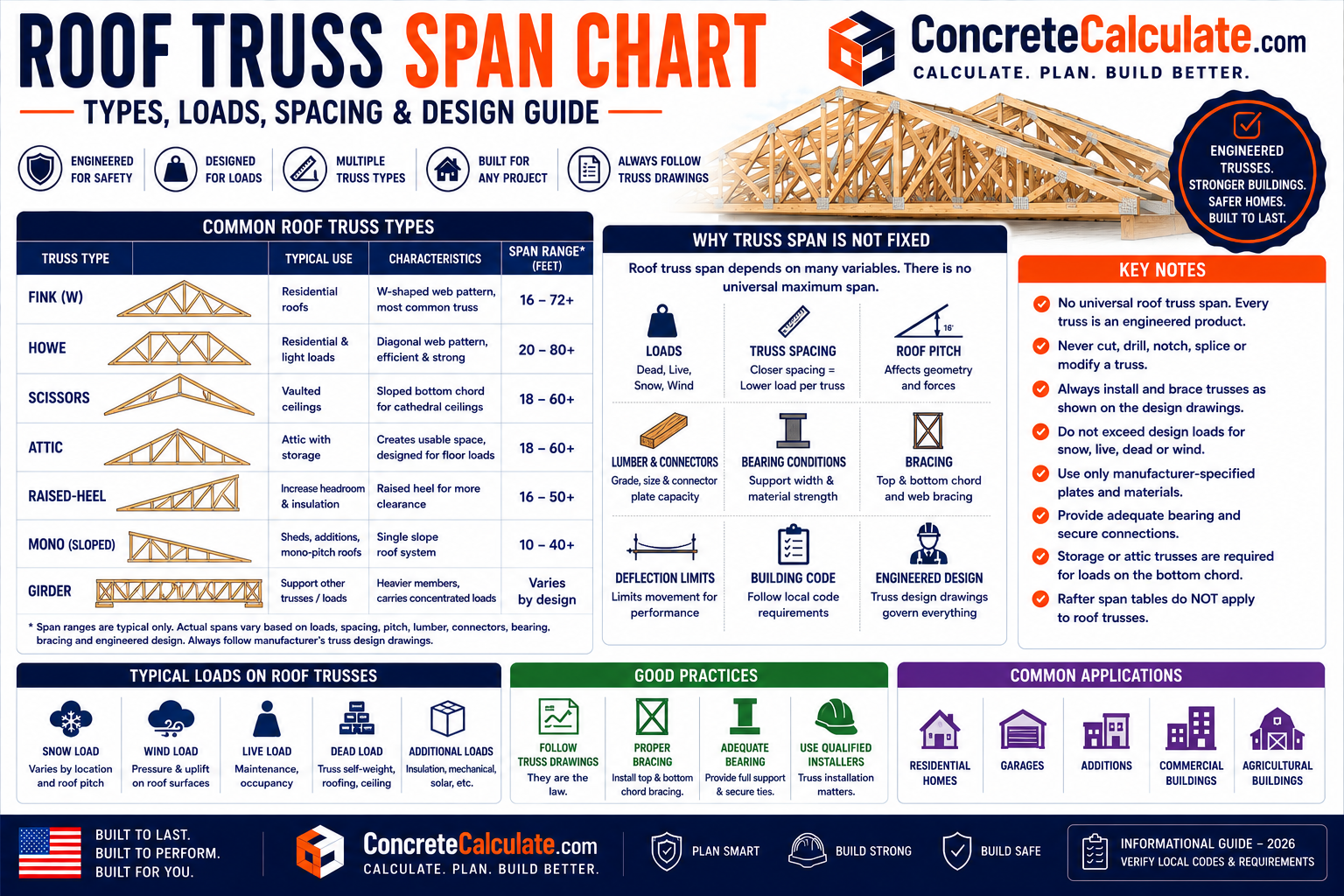
Roof Truss Span Chart
Types, Loads, Spacing & Design Guide
Roof trusses are engineered assemblies, not individual lumber members. Span must be evaluated with truss type, spacing, pitch, loads, bearing, bracing and the actual design drawing.
 Reviewed by Muhammad Ramzan Babar, PhD Researcher & Calculator Developer · View Profile
Modern metal-plate-connected roof trusses are engineered assemblies. Their allowable span depends on truss configuration, chord/web sizes, connector plates, spacing, pitch, loads, bearing, bracing, deflection, and manufacturer design criteria. This page intentionally does not invent generic maximum spans.
⭐⭐⭐ Roof Truss Span Chart: Quick Reference
Use this table to identify the variables required for a legitimate truss span decision. Every row is design-specific, not a universal span value.
| Truss Type | Span | Spacing | Roof Pitch | Load Condition | Truss Depth | Source/Design Basis |
|---|---|---|---|---|---|---|
| Fink | Design-specific | 16″ OC | Design-specific | Dead, live, snow, wind | Design-specific | Manufacturer/engineered truss design |
| Fink | Design-specific | 24″ OC | Design-specific | Dead, live, snow, wind | Design-specific | Manufacturer/engineered truss design |
| Howe | Design-specific | 16″ OC | Design-specific | Dead, live, snow, wind | Design-specific | Manufacturer/engineered truss design |
| Howe | Design-specific | 24″ OC | Design-specific | Dead, live, snow, wind | Design-specific | Manufacturer/engineered truss design |
| Scissors | Design-specific | 16″ OC | Design-specific | Roof + vaulted ceiling loads | Design-specific | Manufacturer/engineered truss design |
| Scissors | Design-specific | 24″ OC | Design-specific | Roof + vaulted ceiling loads | Design-specific | Manufacturer/engineered truss design |
| Attic | Design-specific | Any specified | Design-specific | Roof + bottom chord floor/storage loads | Design-specific | Manufacturer/engineered truss design |
| Girder | Design-specific | Supports other trusses | Design-specific | Concentrated truss reactions | Design-specific | Manufacturer/engineered truss design |
ANSI/TPI 1-2022 establishes minimum requirements for design and construction of metal-plate-connected wood trusses, including materials, truss members and joints, connector plate evaluation, manufacturing quality assurance, and design responsibilities. This edition is referenced in the 2024 International Building Codes.
⭐⭐⭐ What Is a Roof Truss?
A roof truss is an engineered triangulated structural assembly that transfers roof and ceiling loads to bearing supports.
Top chords
Sloped outer members supporting roof sheathing, roofing, snow, wind, and other roof loads.
Bottom chord
Lower member, often supporting ceiling loads and potentially serving as a ceiling framing element.
Web members
Internal diagonal and vertical members that create triangles, distribute forces, and stabilize the complete truss geometry.
Connector plates
Metal-toothed connector plates commonly join chord and web members in modern residential wood trusses.
Bearing points
Locations where truss reactions transfer into exterior walls, beams, or other designed supports.
Engineered assembly
Unlike a single rafter or joist, every member and connector works together, which is why trusses are designed as a complete system.
⭐⭐⭐ What Is Roof Truss Span?
Truss span is the bearing-to-bearing distance, not automatically the overall truss length or building width.
| Term | Meaning |
|---|---|
| Truss span | Distance between the truss’s relevant supporting bearing points |
| Building width | Overall building dimension, often close to but not always identical to truss span |
| Clear span | Open distance between support faces |
| Overall truss length | May include bearing extensions and/or overhang geometry beyond primary span |
| Sloped top chord length | Actual length of the inclined top chord, not the truss’s horizontal span |
⭐⭐⭐ Roof Truss Span vs Rafter Span
Do not use conventional rafter span tables to select an engineered roof truss.
| Feature | Roof Truss | Roof Rafter |
|---|---|---|
| Structural system | Engineered triangulated assembly | Individual framing member |
| Internal webs | Yes | No |
| Typical design | Manufacturer/truss designer engineering | Prescriptive span table or engineering |
| Span determination | Truss-specific design | Lumber size/species/load dependent |
| Design documentation | Truss design drawing | Span table or engineering calculation |
AWC span tables are specifically for joists and rafters under stated lumber and loading conditions. Modern metal-plate-connected roof trusses are engineered assemblies designed with specialized software and truss drawings; do not substitute a rafter table for a truss design.
See the Roof Rafter Span Chart for conventional rafter guidance.
⭐⭐⭐ Roof Truss Span vs Ceiling Joist Span
These spans are not interchangeable even when a truss bottom chord supports ceiling finishes.
Ceiling joist
A repeated linear framing member supporting ceiling loads and potentially acting as a rafter tie when designed and connected correctly.
Roof truss
A complete engineered system whose bottom chord may form part of the ceiling framing, but whose design depends on the interaction of chords, webs, plates, loads and supports.
See the Ceiling Joist Span Chart for conventional ceiling joist spans under specified AWC conditions.
⭐⭐⭐ Roof Truss Types
Configuration affects geometry, loads, internal force distribution, and the type of engineered design required.
| Truss Type | General Configuration / Use |
|---|---|
| Fink | Common residential pitched truss with W-shaped web configuration |
| Howe | Truss configuration with a different web arrangement, used in varied span/design conditions |
| Fan | Multiple web members fanning from a central or lower-chord location |
| King-post / Queen-post | Traditional truss geometries, often used for specific architectural or simpler span configurations |
| Scissors | Sloping bottom chord for vaulted/cathedral ceiling |
| Attic | Creates usable interior space; bottom chord supports floor/storage loads |
| Raised-heel | Increased heel height for insulation depth and energy performance |
| Mono | Single-slope/asymmetric roof geometry |
| Girder | Supports other trusses and concentrated reactions, often multiple-ply |
| Parallel-chord | Parallel top and bottom chords, commonly used for floors or flat roof applications |
Fink truss ⭐⭐⭐
A common residential configuration with W-shaped internal webs. Its span, depth, pitch and chord size remain specific to the truss design; “Fink” identifies geometry, not a universal capacity.
Howe truss ⭐⭐
Defined by its web configuration and used for specific architectural or span conditions. It still requires the complete engineered load, spacing, bearing and connection design.
Scissors truss ⭐⭐⭐
Used for vaulted/cathedral ceilings with a sloping interior bottom chord. It is structurally distinct from flat-bottom trusses and requires its own engineered design.
Attic truss ⭐⭐⭐
Designed for usable attic space, storage, or habitable loads. The bottom chord can act as a floor system, significantly increasing design demands relative to a non-storage truss.
Raised-heel truss ⭐⭐⭐
Provides additional heel height at the eave, allowing greater insulation depth and better energy-efficient roof detailing while retaining an engineered structural system.
Girder truss ⭐⭐⭐
Supports other trusses or framing members and concentrated reactions. It often uses multiple plies and cannot be treated like an ordinary repeated truss.
⭐⭐⭐ Roof Truss Span by Spacing
Spacing changes tributary roof area and therefore load per truss.
| Truss Span Geometry | 12″ OC | 16″ OC | 24″ OC |
|---|---|---|---|
| 20 ft building/truss geometry | Design-specific | Design-specific | Design-specific |
| 24 ft building/truss geometry | Design-specific | Design-specific | Design-specific |
| 30 ft building/truss geometry | Design-specific | Design-specific | Design-specific |
| 40 ft building/truss geometry | Design-specific | Design-specific | Design-specific |
16″ OC ⭐⭐⭐
A common residential spacing. Each truss supports a tributary roof width of approximately 16 inches under typical repeated-truss geometry, but allowable span remains dependent on the complete truss design.
24″ OC ⭐⭐⭐
Wider spacing means each truss supports more tributary roof area than at 16″ OC. This additional load must be included in the engineered truss design; do not assume identical truss capacity at 24″ OC.
For a typical repeated truss system, tributary width is approximately the truss spacing. Wider spacing increases the roof area, and therefore roof load, assigned to each truss.
⭐⭐⭐ Roof Truss Span by Roof Pitch
Pitch changes truss geometry but does not establish an allowable span by itself.
Common pitches
2:12, 3:12, 4:12, 5:12, 6:12, 8:12, 10:12 and 12:12 all create different top-chord geometry and internal member force patterns.
Pitch effects
Higher pitch creates different chord lengths, truss rise, web geometry, possible member forces, and design requirements. The complete load and support design still controls actual span capacity.
See the Roof Pitch Chart for pitch-to-angle, rafter factor, and roof area geometry reference.
⭐⭐⭐ Roof Truss Span and Truss Depth
Span, depth, rise and web geometry work together in truss design.
Truss depth
Deeper trusses can often provide more efficient structural geometry for a given span, but this does not create a universal “span-to-depth” rule or code requirement.
Span-to-depth relationship
Designers consider the relationship between span and truss depth as part of member force, deflection, web layout, fabrication and transportation optimization, always under the specific design loads and criteria.
Truss rise
For simple symmetrical geometry: rise = horizontal half-span x (roof pitch rise/run). This calculates physical geometry, not allowable structural span.
Chord and web sizes
Chord size, web size, lumber grade, design values, and connector plates all contribute to capacity; a “2×4 truss” label alone cannot determine span.
⭐⭐⭐ Roof Truss Span and Loads
Load condition is one of the primary design inputs for engineered trusses.
Dead load
Roof sheathing, roofing, underlayment, insulation, ceiling materials, truss self-weight, mechanical systems and permanently attached equipment.
Roof live load
Design-condition-dependent roof live load from the applicable code, not a universal value.
Snow load
Ground snow load, roof snow load, drift, accumulation, geometry, exposure and thermal conditions all matter. Never use one universal snow load for every location.
Wind load and uplift
Wind pressure, uplift, building height, exposure, roof geometry, connection details and wind zone determine the uplift design condition.
Ceiling load
Bottom chord may carry drywall, plaster, insulation, fixtures and other ceiling-related loads.
Additional loads
Attic storage, mechanical equipment, solar panels, and suspended loads need specific review because they can change the original truss design condition.
The 2024 WFCM incorporates roof-system provisions based on ASCE 7-22 load criteria, including ground snow loads from 0 to 70 psf (ASD) and basic wind speeds from 90 to 195 mph 3-second gust. Actual local design conditions still govern each truss project.
⭐⭐⭐ Attic, Solar, HVAC and Additional Loads
Added loads can fundamentally change a truss design condition.
Attic storage and attic trusses
A storage or attic truss must be designed for bottom-chord floor/storage loads, usable space, stair openings and possibly habitable loads. A non-storage roof truss should never be assumed capable of carrying attic flooring or storage.
Solar panels ⭐⭐⭐
Panel weight, mounting system, concentrated attachment loads, wind uplift and roof geometry all require evaluation against the original truss design. Existing truss span alone does not establish solar capacity.
HVAC and suspended loads
Ductwork, mechanical equipment, suspended loads and service openings can introduce concentrated or additional loads that must be evaluated by the truss designer or qualified engineer.
Roofing materials
Asphalt shingles, metal, clay tile, concrete tile and slate have different dead loads. A heavier roofing material can require a different truss design even at the same span and pitch.
⭐⭐⭐ Roof Truss Bearing and Support Conditions
Truss reactions must transfer safely into walls, beams, or girder trusses.
Bearing locations
Common support arrangements include exterior wall to exterior wall, wall to beam, girder truss support, interior bearing, and multiple bearing points.
Bearing length
Required bearing depends on truss reaction, supporting material, compression perpendicular to grain, building code, and manufacturer/design requirements. Do not use a single universal bearing length.
End reactions
Truss design drawings identify reactions at each bearing point, which must be carried through the supporting wall, beam and foundation load path.
Overhang
Truss span is not the same as roof overhang. A truss can extend beyond the bearing line as designed, but overhang geometry needs to be part of the engineered truss layout.
Equipment for Your Project
Affiliate disclosure: As an Amazon Associate, ConcreteCalculate earns from qualifying purchases. We may also earn a commission from other affiliate links at no additional cost to you.
⭐⭐⭐ Roof Truss Bracing and Stability
Truss span capacity cannot be separated from temporary and permanent bracing.
Temporary bracing
Required during installation to keep trusses aligned and stable before permanent bracing, sheathing and roof diaphragm action are fully established. Follow the truss package and installation/bracing plan, not a generic site pattern.
Permanent bracing
May include lateral restraint, diagonal bracing, web bracing, top-chord bracing and bottom-chord bracing, as specified on the truss design drawings and bracing documentation.
Web restraint
Some webs may require specific continuous lateral restraint and diagonal bracing depending on their compression forces and truss design requirements.
Truss-specific requirement
Bracing is design-specific. Do not create or follow one universal bracing pattern for every truss package without checking the truss designer and applicable bracing documentation.
⭐⭐⭐ Roof Truss Design Drawings
The truss design drawing is the primary document for actual truss span and installation requirements.
| Drawing Item | What It Identifies |
|---|---|
| Truss ID | Unique truss identification number/type |
| Span and overall dimensions | Bearing-to-bearing geometry and overall truss layout |
| Heel and pitch | Roof geometry and eave configuration |
| Bearing | Support locations and reactions |
| Member sizes and webs | Chord/web configuration and lumber specification |
| Connector plates | Plate locations, sizes and connection design |
| Loads/design criteria | Dead, live, snow, wind and special loads |
| Bracing requirements | Required restraint and bracing information |
Look for the truss number, type, span, pitch, bearing points, heel details, special loads, web layout, and any bracing notes on the design drawing. This document is more authoritative for a specific truss than a generic web chart.
⭐⭐⭐ How Roof Truss Span Is Determined
Manufactured truss span is not calculated from a simple truss-length formula.
Define span, pitch, rise, overhang, bearing and truss type.
Define dead, live, snow, wind uplift, ceiling and special loads.
Assign the roof area and loads carried by each repeated truss.
Define bearing points, reactions and load path into walls or beams.
Analyze chord and web forces under applicable load combinations.
Select lumber, connector plates and configuration for all force conditions.
Verify serviceability, camber where applicable, and bracing requirements.
Issue engineered truss design drawing and installation/bracing requirements.
This workflow reflects why a manufactured roof truss should not be sized using a generic “2×4 or 2×6 truss span” chart. Specialized design software calculates structural load conditions and member/plate requirements for the complete assembly.
⭐⭐⭐ Roof Truss Span by Building Width
Building width is useful geometry context, not a universal capacity category.
| Building/Geometry Width | What Must Still Be Defined |
|---|---|
| 16 ft | Truss type, pitch, spacing, loads, bearing, bracing, design source |
| 20 ft | Truss type, pitch, spacing, loads, bearing, bracing, design source |
| 24 ft | Truss type, pitch, spacing, loads, bearing, bracing, design source |
| 30 ft | Truss type, pitch, spacing, loads, bearing, bracing, design source |
| 32 ft | Truss type, pitch, spacing, loads, bearing, bracing, design source |
| 40 ft | Truss type, pitch, spacing, loads, bearing, bracing, design source |
| 50 ft+ | Long-span engineering, handling, transport and bracing review |
Small residential spans
Common residential building widths such as 20, 24, 28, 30 and 32 feet can all use engineered trusses, but each truss remains specific to the actual loading, pitch, spacing and design documentation.
Long-span roof trusses ⭐⭐⭐
Longer spans such as 40 feet and above increase engineering complexity, deflection sensitivity, bracing needs, connection demands, transportation considerations and installation/handling requirements. There is no single universal “maximum roof truss span.”
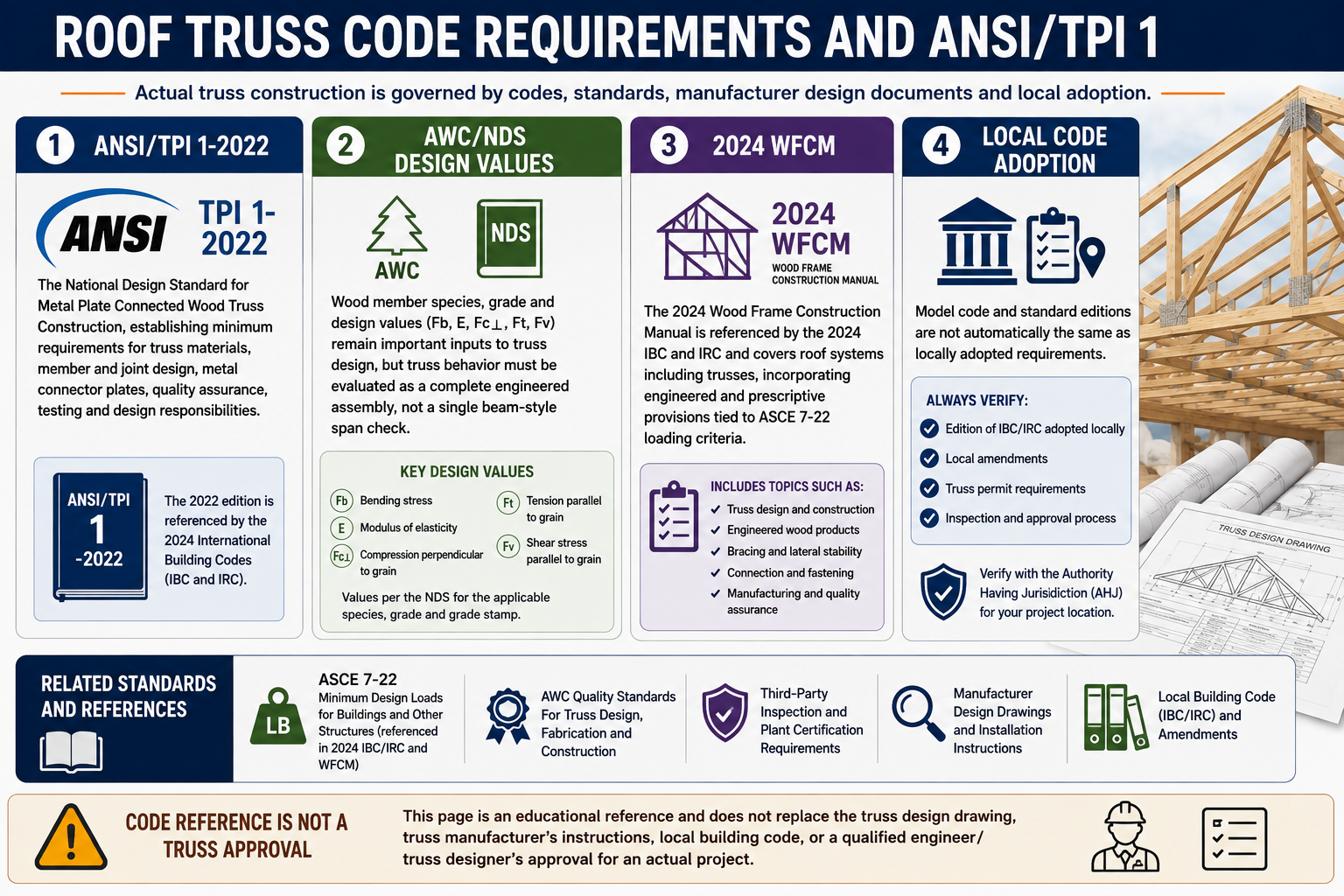
⭐⭐⭐ Roof Truss Code Requirements and ANSI/TPI 1
Actual truss construction is governed by codes, standards, manufacturer design documents and local adoption.
ANSI/TPI 1-2022
The National Design Standard for Metal Plate Connected Wood Truss Construction, establishing minimum requirements for truss materials, member and joint design, metal connector plates, quality assurance, testing and design responsibilities. The 2022 edition is referenced by the 2024 International Building Codes.
AWC/NDS design values
Wood member species, grade and design values (Fb, E, Fc⊥, Ft, Fv) remain important inputs to truss design, but truss behavior must be evaluated as a complete engineered assembly, not a single beam-style span check.
2024 WFCM
The 2024 Wood Frame Construction Manual is referenced by the 2024 IBC and IRC and covers roof systems including trusses, incorporating engineered and prescriptive provisions tied to ASCE 7-22 loading criteria.
Local code adoption
Model code and standard editions are not automatically the same as locally adopted requirements. Verify the edition, local amendments and permit requirements with the authority having jurisdiction.
This page is an educational reference and does not replace the truss design drawing, truss manufacturer’s instructions, local building code, or a qualified engineer/truss designer’s approval for an actual project.
⭐⭐⭐ Manufactured vs Site-Built Trusses
Fabrication method changes documentation, connection design and quality control requirements.
| Feature | Manufactured | Site-Built |
|---|---|---|
| Fabrication | Factory | Jobsite |
| Engineering | Manufacturer/truss designer | Designer/engineer |
| Connections | Engineered metal connector plates | Site-specific designed connections |
| Documentation | Truss design drawings | Construction/engineering drawings |
| Span | Design-specific | Design-specific |
A truss configuration image, a generic web layout or an example truss drawing does not contain the complete project loading, plate, member and bracing design required to safely fabricate a truss.
⭐⭐⭐ Truss Modifications and Added Loads
Changes after truss fabrication require professional review.
Can you cut a roof truss? ⭐⭐⭐
Do not cut, drill, notch, splice or otherwise modify a manufactured roof truss without written approval from the truss designer or qualified engineer. Even a small modification can compromise the engineered load path through chords, webs, or connector plates.
Can you add loads? ⭐⭐⭐
Solar panels, HVAC equipment, storage, heavy ceiling finishes, hanging equipment and new openings should be evaluated against the original truss design. Span alone does not establish capacity for these additions.
Attic storage
Adding flooring or storage to an existing non-storage truss can overload the bottom chord. Use a truss designer or engineer to evaluate before adding load.
Field changes
Do not relocate bearing, remove web members, add concentrated loads, or alter connector plates without documented engineering approval.
⭐⭐⭐ Roof Truss Span Visual Guide
Original diagrams explaining truss anatomy, load path, geometry, and spacing.
See the itemized image list below for exact placement, subject and caption for each recommended photograph.
⭐⭐⭐ Roof Truss Span Worked Examples
These examples demonstrate geometry and design variables, not universal truss capacities.
1. Determine Geometric Span
2. Calculate Truss Rise
3. Determine Sloped Top-Chord Geometry
4. Compare 16″ and 24″ OC Spacing
5. Adding Attic Storage
⭐⭐⭐ Common Roof Truss Span Mistakes
Most unsafe truss assumptions trace back to one of these errors.
❌ Treating a truss like a single beam
A truss is a multi-member engineered assembly, not one bending member.
❌ Assuming span from truss depth alone
Depth helps define geometry but does not establish universal capacity.
❌ Using rafter tables for trusses
Rafter span tables are for individual framing members, not engineered truss assemblies.
❌ Using floor joist tables for trusses
Floor joist tables are unrelated to truss chord/web/plate design.
❌ Ignoring spacing
Spacing changes tributary roof area and load per truss.
❌ Ignoring snow and wind uplift
Both can govern truss forces and connections depending on location and roof geometry.
❌ Ignoring attic/storage loads
Bottom chord loading can change completely when storage or usable attic space is added.
❌ Ignoring truss drawings
The design drawing is the controlling project document for the individual truss.
❌ Cutting or modifying truss members
Modifications can compromise the engineered load path and require approval.
❌ Adding concentrated loads without approval
Solar, HVAC and hanging loads must be evaluated against the design.
❌ Ignoring bracing
Truss stability and span capacity depend on required temporary and permanent bracing.
❌ Assuming all Fink trusses are identical
Fink identifies a geometry type, not a universal capacity or span.
❌ Assuming 16″ and 24″ OC have same capacity
Wider spacing increases tributary load per truss.
❌ Treating a manufacturer example as universal
Manufacturer tables/examples are only valid under their stated loads, spacing, pitch, and design criteria.
Frequently Asked Questions
📄 Download Roof Truss Span Chart PDF
This PDF is a truss engineering field reference, not a generic unsupported maximum-span list. Actual projects require manufacturer design drawings and the applicable engineering documentation.
Cite or Embed This Chart
Copy the page-wide citation to reference the complete Roof Truss Span Chart.