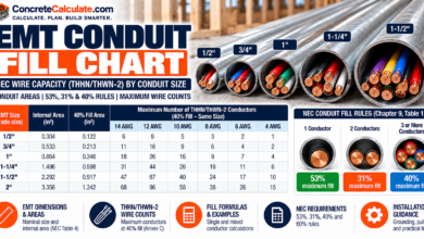
Screw Head Types Chart – Shapes, Uses & Drive Comparison
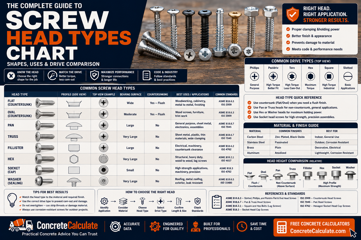
Screw Head Types Chart
Shapes, Uses & Drive Comparison
The complete screw head reference: flat, pan, oval, truss, fillister, hex, socket, and washer heads compared by profile, bearing surface, countersinking, and application.
 Reviewed by Muhammad Ramzan Babar, PhD Researcher (Plasma Physics) & Calculator Developer, View Profile
Head shape does not rank screw strength
This chart describes head geometry, bearing surface, and typical applications. Head type alone does not determine screw strength or structural capacity; material, grade, diameter, thread, coating, and the specific product’s tested design values all matter separately.
Screw Head Types Chart, Quick Reference
These are standardized head forms recognized in ASME B18.6.3 and related ISO standards, distinguished from common manufacturer/product marketing terminology.
| Head Type | Head Profile | Countersunk? | Bearing Surface | Typical Drive | Common Applications |
|---|---|---|---|---|---|
| Flat/countersunk | Flat top, conical underside | Yes | Conical | Phillips, slotted, Torx | Flush wood/metal fastening |
| Oval/raised countersunk | Rounded top, conical underside | Yes | Conical | Phillips, slotted | Decorative flush fastening |
| Pan | Flat top, cylindrical sides | No | Flat | Phillips, slotted, Torx | General machine/tapping screws |
| Round | Domed/semi-elliptical | No | Flat | Slotted, Phillips | General/legacy applications |
| Truss | Low rounded, wide diameter | No | Flat, large | Phillips, Torx | Thin/soft material fastening |
| Fillister | Rounded top, tall cylindrical sides | No | Flat | Slotted, Phillips | Machine screw applications |
| Binding | Rounded top, tapered sides | No | Flat | Slotted, Phillips | Machine screws, terminal connections |
| Hex | Six-sided external head | No | Flat, large | External hex (wrench/socket) | High-torque wood/construction fastening |
| Hex washer | Hex head with integral washer | No | Flat, very large | External hex | Sheet metal, structural wood connections |
| Round washer | Rounded crown with integral washer | No | Flat, large | Slotted, Phillips | Sheet metal, general fastening |
| Button | Low rounded/domed profile | No | Flat, moderate | Socket hex, Torx | Machine/assembly applications |
| Socket head cap | Cylindrical head | No | Flat | Internal hex socket | High-strength machine applications |
Head forms per ASME B18.6.3, Slotted and Recessed Head Machine Screws, and related ISO standards. Not every commercially marketed head name (such as “bugle head”) is an independent ASME/ISO standardized category; some are product/industry terminology describing a specific profile within these broader forms.
What Is a Screw Head?
The screw head is the portion of the fastener that transfers installation torque and bears against the material surface, distinct from the shank and threaded body.
The head performs two main functions: it provides a drive/recess feature that a tool engages to transmit rotational force during installation, and it provides a bearing surface that presses against the material to hold the connection together. Head height and head diameter both affect how the screw performs, appears, and fits within a given application, including whether adequate installation access and tool clearance exist.
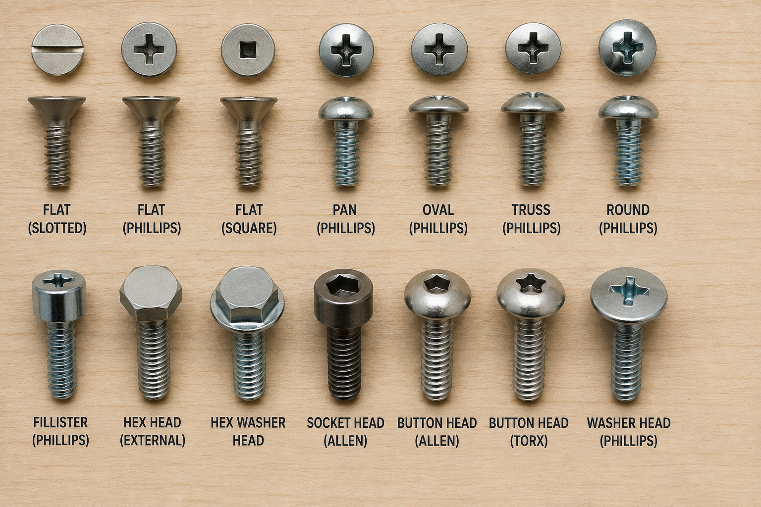
Screw Head Types vs Screw Drive Types
Head shape and drive pattern are independent characteristics. The same head shape can come with several different drive types.
| Head Type | Possible Drive Type |
|---|---|
| Pan head | Phillips |
| Pan head | Slotted |
| Pan head | Torx |
| Flat head | Phillips |
| Flat head | Torx |
| Hex head | External hex |
| Socket head | Internal hex |
| Truss head | Phillips/Torx/etc. |
A very common misunderstanding
Saying “I need a Phillips screw” only describes the drive, not the head shape. A pan head, flat head, and truss head can all be manufactured with a Phillips drive. This page focuses primarily on head geometry, while the Screw Head Drive Types section covers drive/recess systems separately.
Screw Head Anatomy
Every screw head shares the same basic anatomical features, though their proportions vary by head type.
Flat Head / Countersunk Screw
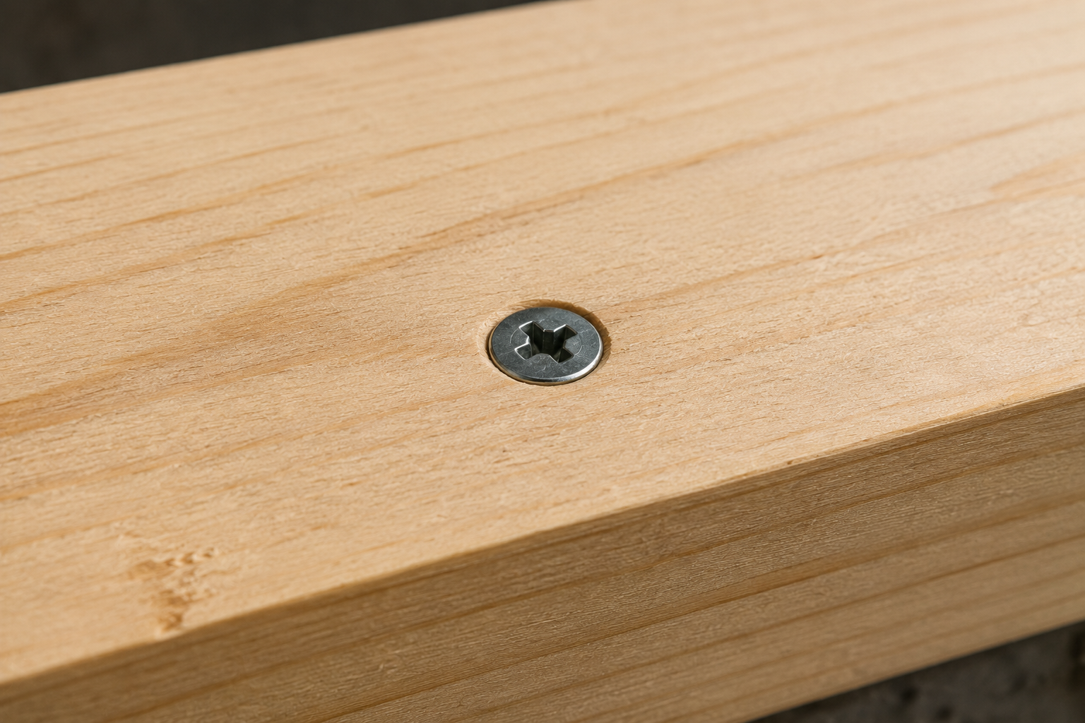
The flat head has a flat top surface and a conical bearing surface, designed to seat flush with the material surface within a matching countersink.
ASME B18.6.3 defines the flat countersunk head as having a flat top surface and a conical bearing surface with a head angle of approximately 82 degrees for one style and approximately 100 degrees for another. Flush installation depends on matching the screw’s head angle to the countersink angle in the material, since a mismatched angle can leave the head sitting either above the surface or seated unevenly with contact concentrated at only the outer edge.
Flat Head Screw Angle, 82 vs 90 vs 100 Degrees
Countersunk heads are not all the same angle, and matching the correct angle to the correct standard is essential for a proper flush fit.
| Angle | Common Standard | Typical Application |
|---|---|---|
| 82 degrees | ASME B18.6.3, inch-series (ANSI/Unified) | General US hardware, construction, automotive |
| 90 degrees | ISO 7046/10642, metric | Global metric assemblies |
| 100 degrees | Aerospace (MS/NAS specifications) | Thin sheet aircraft skins, composites |
Do not assume any countersink tool fits any flat head screw
An 82 degree screw seated in a 90 degree countersink contacts only the outer edge of the conical surface, appearing flush while actually bearing unevenly. Confirm the actual screw standard (inch versus metric versus aerospace) before selecting a countersinking tool or drill bit angle.
Oval Head / Raised Countersunk Screw
The oval head combines a conical countersunk underside with a rounded, raised top, giving a slightly domed appearance rather than a fully flat finish.
ASME B18.6.3 separately defines oval countersunk head forms, including trim-head variants with a smaller head diameter than the standard oval head. ISO 7047 covers raised countersunk head screws in the metric system. Oval heads are commonly chosen for a more finished or decorative appearance compared to a fully flat head, while still seating within a countersunk hole.
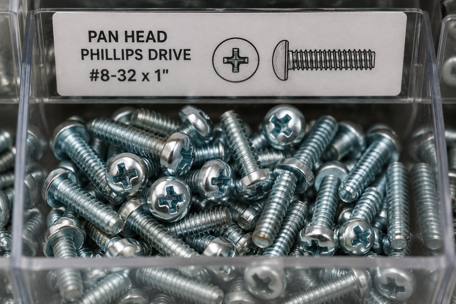
Pan Head Screw
The pan head has a rounded top surface blending into cylindrical sides with a flat bearing surface, remaining above the material surface without countersinking.
ASME B18.6.3 describes the pan head as having a rounded top surface blending into cylindrical sides and a flat bearing surface, one of the most common head types for general machine and tapping screw applications where a flush finish is not required.
Round Head Screw
The round head has a domed, semi-elliptical profile with a flat bearing surface, distinct from but sometimes dimensionally overlapping with the pan head.
ASME B18.6.3 separately defines round head screws and notes some dimensional overlap with pan head proportions. Round heads have historically been common in older hardware and remain used in some general and decorative applications today, though pan heads have become more prevalent in modern machine screw manufacturing.
Truss Head Screw
The truss head has a low rounded profile with a bearing diameter larger than the corresponding round head, providing increased bearing area for applications needing a wider head.
ASME B18.6.3 defines the truss head as having a low rounded top with a flat bearing surface whose diameter, for a given screw size, is larger than the corresponding round head. This increased bearing area makes truss heads useful for thinner or softer materials where reducing localized bearing pressure helps prevent pull-through.
Fillister Head Screw
The fillister head has a rounded top, tall cylindrical sides, and a flat bearing surface, giving it a taller profile than a pan head of the same diameter.
ASME B18.6.3 defines the fillister head with dimensional tables separate from pan and round heads, and also covers drilled fillister head machine screws as a distinct variant. The taller profile can provide more material for the drive recess in smaller screw sizes and is common in certain machine screw applications.
Binding Head Screw
The binding head has a rounded top with slightly tapered sides and a flat bearing surface, used in certain machine screw and terminal/wire connection applications.
ASME identifies binding heads as applicable to machine screws within its standard, sometimes including an optional annular undercut adjacent to the shank. Binding heads appear in specific electrical terminal and machine assembly applications where their particular bearing profile is useful.
Hex Head Screw
The hex head has a six-sided external head designed for wrench or socket installation, providing higher installation torque capacity than typical bit-driven heads.
| Characteristic | Benefit |
|---|---|
| Six-sided external head | Wrench or socket engagement rather than a bit recess |
| Large bearing surface | Distributes load over a wider area than small drive recesses allow |
| High installation torque | Useful when a driver bit cannot supply sufficient torque |
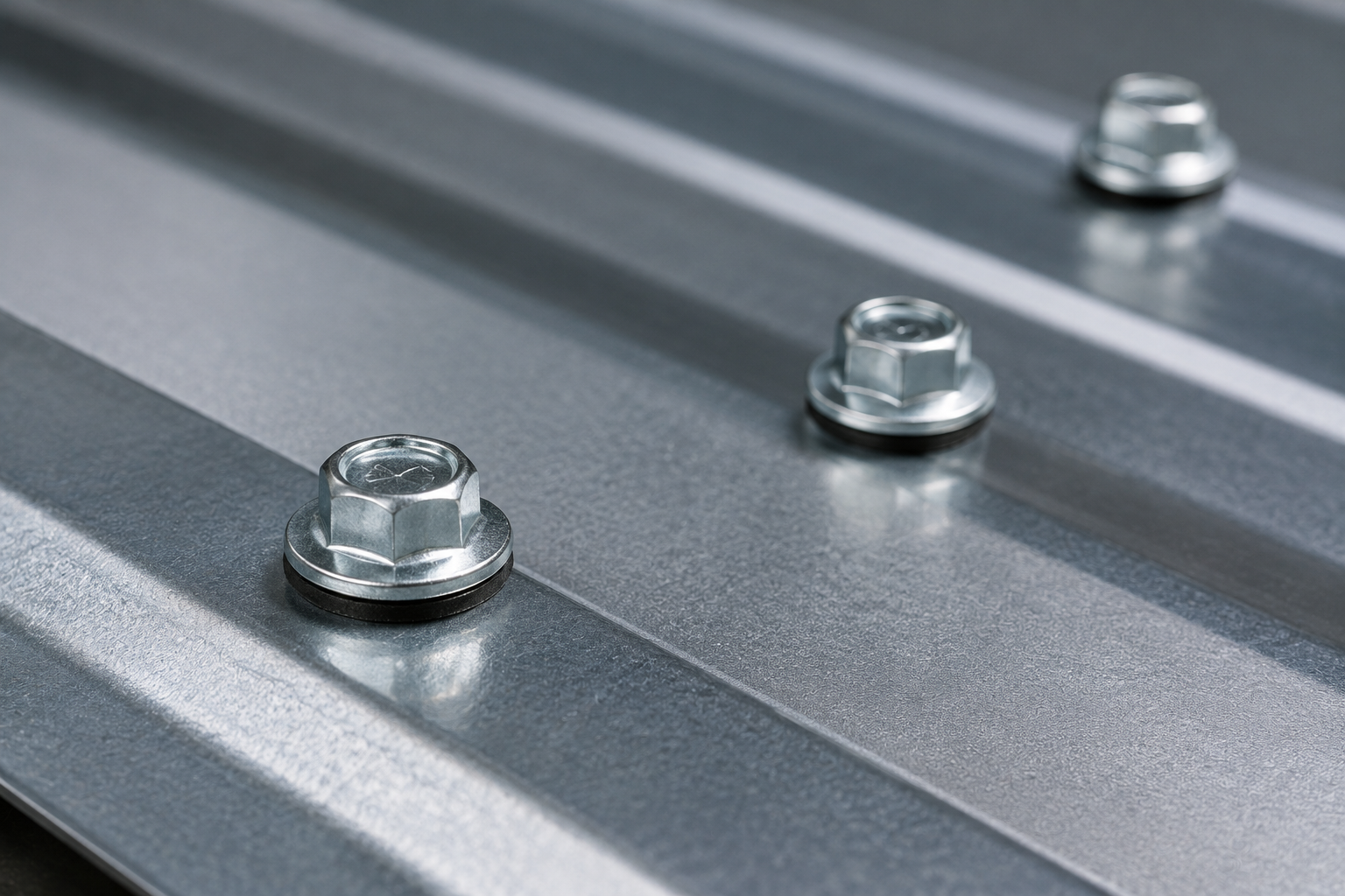
Hex Washer Head Screw
The hex washer head combines a hex drive with an integral washer-like bearing surface, increasing bearing area and reducing pull-through risk compared to a standard hex head.
ASME B18.6.3 specifically defines the hex washer head as a hex head formed integrally with a projecting washer that provides the bearing surface. This combination makes hex washer heads especially common in sheet metal and construction applications where both wrench-driven installation and a larger bearing footprint are needed.
Round Washer Head Screw
The round washer head has a rounded crown combined with an integral washer, increasing bearing surface compared to an ordinary round head.
ASME B18.6.3 separately defines round washer heads from standard round heads, since the integral washer feature meaningfully changes the bearing characteristics even though the top profile appears similar.
Button Head Screw
The button head has a low, rounded, domed profile, often used in socket or Torx drive configurations where reduced snagging and a smoother appearance are desired.
Button head vs round head, a naming distinction
Button head and round head can sound similar, but manufacturers and standards distinguish them: button heads are typically lower profile and paired with socket or Torx drives in machine/assembly contexts, while round heads follow ASME B18.6.3’s more traditional slotted/Phillips-era profile. Terminology can vary between manufacturers, so verify the actual dimensional specification when precision matters.
Socket Head Cap Screw
The socket head cap screw has a cylindrical head with an internal hex socket, distinct from an external hex head, and is common in high-strength machine applications.
| Feature | Socket Head Cap Screw | Hex Head |
|---|---|---|
| Drive location | Internal recess (hex key) | External flats (wrench/socket) |
| Head shape | Cylindrical | Hexagonal |
| Access needed | Can work in recessed/limited-access holes | Needs clearance for wrench/socket around the head |
This distinction resolves a very common point of confusion: socket head and hex head are not the same thing, even though both commonly use a hexagonal drive feature, because one places the hex internally (a recess) and the other externally (the head shape itself).
Low-Profile and Trim Head Screws
Trim and low-profile heads reduce head diameter or height compared to their standard counterparts, useful for finish appearance or limited material thickness.
ASME B18.6.3 explicitly includes flat and oval countersunk trim heads, whose head size is smaller than the regular corresponding countersunk head, intended for applications where a less visually prominent or more compact head is desired without changing the fundamental countersunk profile.
Washer Head vs Standard Head
Integrated washer heads provide a larger bearing surface than standard heads of the same drive type, directly affecting pull-through resistance in soft or thin materials.
| Feature | Standard Head | Washer Head |
|---|---|---|
| Bearing area | Smaller | Larger, integrated washer surface |
| Pull-through resistance | Lower in thin/soft materials | Higher due to distributed load |
| Common application | General fastening | Sheet metal, structural wood, softer materials |
Countersunk vs Non-Countersunk Screw Heads
This is one of the most fundamental distinctions for beginners: whether the head sits flush within the material or remains above the surface.
| Feature | Countersunk | Non-Countersunk |
|---|---|---|
| Head position | Flush/recessed within the surface | Remains above the surface |
| Surface preparation | Usually requires a countersunk hole | Usually not required |
| Examples | Flat, oval | Pan, round, truss, hex, socket |
| Typical advantage | Flush finish, no head protrusion | Simpler installation, no countersinking step |
Screw Head Types by Installation Surface
Grouping head types by installation surface requirement gives a practical selection framework rather than an arbitrary list.
| Installation Need | Suitable Head Types |
|---|---|
| Flush surface | Flat, oval |
| Surface-mounted (protrudes above surface) | Pan, round, truss, button |
| Heavy bearing surface | Washer head, hex washer head |
| Mechanical assembly (limited access/high torque) | Socket head, hex head, fillister |
Screw Head Types by Application
Head type alone does not determine suitability for an application; material, grade, thread, coating, length, diameter, and drive all matter together.
| Application | Commonly Used Heads |
|---|---|
| Woodworking | Flat, oval, pan, trim, washer head |
| Decking | Flat/trim, manufacturer-specific composite heads |
| Drywall | Bugle-style (product-specific profile) |
| Sheet metal | Pan, hex washer, modified truss |
| Roofing | Hex washer, self-drilling variants |
| Electrical/electronics | Pan, fillister, binding |
| Machinery | Socket, hex, pan, fillister |
| Structural wood connections | Hex, hex washer, structural screw heads |
Screw Head Types for Wood
Flat/countersunk, oval, pan, trim, and washer heads all appear across different wood fastening applications, chosen based on flush requirements and bearing needs.
For dimensional reference on wood screw sizing and identification, see the Wood Screw Size Chart, and for exterior deck-specific fastening, see the Deck Screw Size Chart.
Screw Head Types for Decking
Decking uses flat/trim heads for wood boards, but composite decking often requires manufacturer-specific color-matched heads or hidden fastener systems.
No single head type suits every decking product
Composite decking manufacturers frequently specify particular head profiles designed for flush installation without countersinking, since countersinking can damage the composite cap layer. This makes decking one application where product-specific fastener requirements matter more than a general head type recommendation. See the Deck Screw Size Chart for the fuller decking fastener discussion.
Screw Head Types for Drywall
Drywall screws commonly use a bugle-style head, a tapered underside profile designed to countersink into gypsum board without tearing the paper facing.
The bugle head’s gradually tapered underside reduces surface damage compared to a sharply angled countersunk head, allowing the screw to seat slightly below the drywall surface for finishing compound while minimizing paper face tearing. Bugle head is common industry terminology describing this profile rather than a single universal ASME head classification applied identically across all fastener families. See the Drywall Screw Size Chart for complete drywall fastener sizing.
Screw Head Types for Sheet Metal
Sheet metal applications commonly use pan, hex washer, modified truss, and flat heads, chosen for bearing surface and pull-through resistance in thin material.
| Consideration | Relevance to Sheet Metal |
|---|---|
| Bearing surface | Larger surface reduces local stress on thin material |
| Sheet thickness | Thinner material benefits more from washer-style heads |
| Drive access | External hex allows higher torque for self-drilling screws |
Screw Head Types for Structural Wood Connections
Large washer-style heads and hex heads are common in structural wood connections, but head geometry does not establish structural capacity by itself.
Head shape is not a capacity rating
Structural screw capacities are product-specific and depend on the tested/evaluated fastener and connection, not simply the head shape. A large hex washer head aids load transfer and pull-through resistance, but the actual structural design value comes from the manufacturer’s tested data or the applicable design standard, not from head geometry alone.
Screw Head Types and Bearing Area
A larger bearing surface reduces local bearing pressure for the same applied force, which is why washer heads are chosen for thin or soft materials.
- Larger head diameter increases bearing area
- Lower bearing pressure reduces pull-through risk in soft or thin materials
A larger head does not make the whole screw stronger
Bearing area affects how load transfers into the material surface beneath the head, but it does not change the screw’s shank strength, thread engagement, or overall tensile capacity. A wide head on an otherwise weak or undersized screw does not compensate for inadequate diameter, material, or thread engagement elsewhere in the fastener.
Screw Head Diameter vs Head Height
Both dimensions matter independently for clearance, appearance, pull-through resistance, and tool access.
| Head Characteristic | Primary Consideration |
|---|---|
| Low-profile heads | Clearance in tight spaces, reduced snagging |
| Wide heads | Increased bearing area, pull-through resistance |
| Tall heads | More material for deep drive recesses, higher torque tolerance |
| Standard heads | Balance of general-purpose characteristics |
Screw Head Drive Types
Drive systems are separate from head shape, covering the recess or external feature a tool engages to turn the screw.
| Drive Type | Characteristic |
|---|---|
| Slotted | Single straight slot, prone to cam-out, simple tooling |
| Phillips | Cross-shaped recess, self-centering, moderate cam-out resistance |
| Pozidriv | Modified cross recess with additional engagement, less cam-out than Phillips |
| Square/Robertson | Square recess, strong bit engagement, low cam-out |
| Hex socket (internal) | Hexagonal recess, high torque, used with socket head cap screws |
| Hex external | Hexagonal head shape driven by wrench/socket |
| Torx/hexalobular | Six-lobed recess, excellent bit engagement, minimal cam-out |
| Combination drives | Accept more than one driver type (e.g., Phillips/slotted) |
| Security/tamper-resistant | Specialized pin or asymmetric recess requiring a matching tool |
ASME B18.6.3 covers slotted and recessed head screws and recognizes several driving provisions, with the current standard also including gaging information for recessed heads to help ensure proper tool fit and torque transfer.
Screw Head vs Drive Type, Examples
These combinations reinforce that head shape and drive pattern are chosen independently for a given product.
| Head + Drive Combination | Common Context |
|---|---|
| Pan head + Phillips | General machine/tapping screws |
| Pan head + Torx | Modern assembly applications favoring reduced cam-out |
| Flat head + Phillips | General flush wood/metal fastening |
| Flat head + Torx | Higher-torque flush fastening applications |
| Hex washer head + external hex | Sheet metal, structural wood connections |
| Socket head + internal hex | Machine assembly, limited-access installations |
Screw Head Recess Types
Recess design affects cam-out resistance, bit engagement, torque transfer, and tool compatibility.
| Recess Type | Cam-Out Resistance |
|---|---|
| Slotted | Low, prone to slipping under power tools |
| Phillips | Moderate, designed to cam-out at high torque to prevent overdriving |
| Square/Robertson | High |
| Torx/hexalobular | Very high |
| Hex socket | Very high |
Screw Head Size and Driver Selection
Recess/head size determines correct driver or bit size, and this does not scale directly from screw diameter alone.
Phillips drive sizes (such as #1, #2, #3), Torx sizes (such as T15, T20, T25), and hex socket sizes each follow their own sizing conventions tied to the specific recess dimensions, not a simple proportional scale-up from screw shank diameter. Selecting the correct bit or wrench size requires checking the actual recess specification for the fastener rather than estimating from diameter.
Screw Head Types by Standard
Not every commercial head style is governed by one single standard; several standards work together to define the full range of head forms.
| Standard | Scope |
|---|---|
| ASME B18.6.3-2024 | Inch-series machine screws, tapping screws, and metallic drive screws, including multiple head types and driving provisions |
| ASME B18.6.1 | Inch-series wood screws |
| ISO 7045 | Pan head screws with type H or type Z cross recess (metric) |
| ISO 7046 | Countersunk flat head screws (metric) |
| ISO 7047 | Raised countersunk head screws (metric) |
How to Choose the Right Screw Head
A structured decision process is more reliable than picking a head type by appearance alone.
Determine material
Wood, metal, drywall, or composite drives many downstream choices.
Determine flush requirement
Decide whether the head must sit flush with the surface.
Determine required bearing area
Thin or soft materials may need a washer-style head.
Determine installation access
Confirm whether a bit, wrench, or socket can reach the fastener.
Select head profile
Choose from the standardized forms matching the above requirements.
Select drive type
Choose independently from head profile based on tool availability and torque needs.
Check manufacturer/standard requirements
Confirm the specific product’s published specifications.
Confirm corrosion/material compatibility
Verify coating and base material suit the exposure environment.
Verify the application
Confirm the final selection against the actual project requirements.
Screw Head Selection by Project Type
Common project types and their typical head selection patterns, as a practical starting reference.
| Project Type | Common Head Selection |
|---|---|
| Furniture | Low-profile/decorative/countersunk options |
| Decking | Manufacturer-specific flush/trim or hidden systems |
| Drywall | Bugle-style heads |
| Sheet metal | Pan/washer/hex washer heads |
| Machinery | Socket, hex, pan, fillister |
| Wood construction | Flat, trim, pan, washer, and structural screw heads |
Common Screw Head Problems and Installation Mistakes
The most frequent errors in screw head selection and installation.
Overdriving
Can strip the recess, damage the material surface, or crush composite caps.
Underdriving
Leaves the head proud of the surface, a snagging or trip hazard.
Incorrect countersink angle
A mismatched countersink causes uneven bearing or a non-flush finish.
Using the wrong driver bit
Causes cam-out, stripped recesses, or damaged fastener heads.
Stripping the recess
Makes the fastener difficult or impossible to remove later.
Head protrusion
An unintended non-flush installation where flush was required.
Excessive countersinking
Removes too much material and weakens the surrounding surface.
Pull-through
Occurs when bearing area is inadequate for the material and load.
Using the wrong head for thin material
Small-diameter heads can pull through where a washer head is needed.
Using a decorative head where structural performance is required
Head appearance does not substitute for tested structural design values.
Screw Head Types Worked Examples
These examples teach selection reasoning, not structural design.
Choosing a Flush Head for Wood
Choosing a Head for Thin Sheet Metal
Choosing a High-Bearing-Area Head
Choosing a Head for Limited Tool Access
Choosing Between Pan and Flat Head
Screw Head Types Chart Limitations
This chart describes head geometry and typical applications. It is not a strength ranking or a substitute for product-specific specifications.
Head type alone does not determine screw strength
Material, grade, and thread design matter separately.
Drive type is separate from head type
Both must be selected independently for a given product.
Screw diameter, material, and coating matter
All affect performance beyond head geometry alone.
Installation method matters
Correct countersinking, torque, and drive engagement all affect the result.
Structural screws require product-specific design data
Head shape does not establish tested structural capacity.
Frequently Asked Questions
Download Screw Head Types Chart PDF
Use your browser’s print function to save a curated, print-ready reference sheet: the quick-reference chart, countersink angle comparison, drive type table, and diagrams, without navigation, FAQs, or explanatory prose. This avoids broken file links and stays automatically current.