
How to Build Concrete Forms for a Sidewalk: Layout, Slope, Stakes and Joints
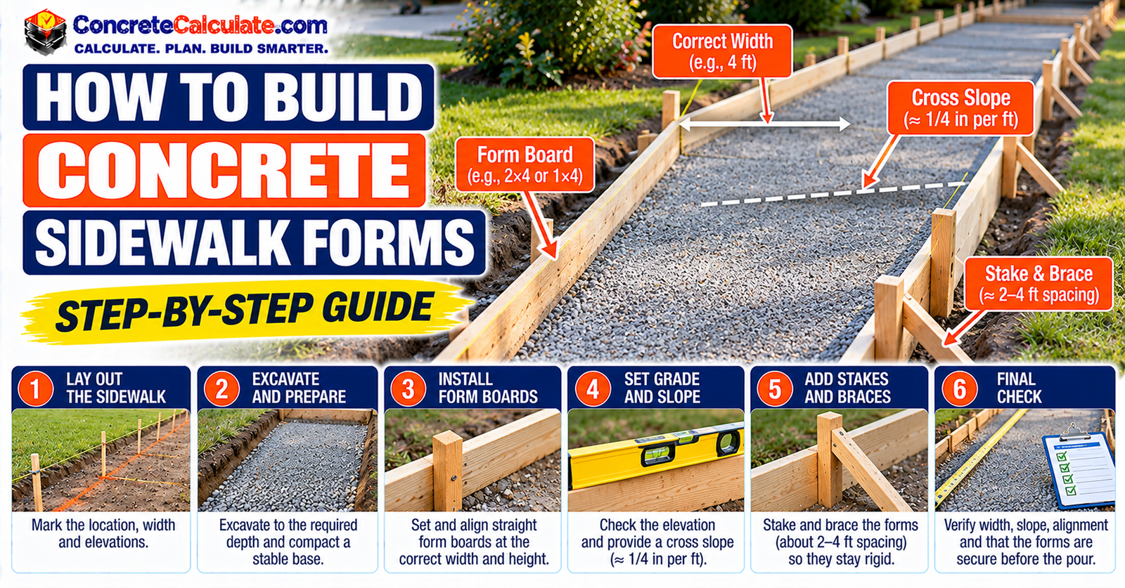
A practical guide to setting rigid, accurately graded sidewalk forms that hold the intended width, edge depth, running grade and cross slope while concrete is placed.
Sidewalk forms must hold three things while concrete is placed: the line, the width and the elevation. Prepare firm support first, then set the first form to line and grade.
Set the second form from the first using the width and a planned cross slope, brace both so they cannot move, and plan the joints before the pour.
Where accessibility rules apply, the U.S. Access Board limits walking surfaces to a 1:20 running slope and a 1:48 cross slope.
- Check site constraints, utilities and the local sidewalk standard.
- Lay out the edges and confirm the inside width.
- Excavate, prepare and compact the support.
- Set the first form, then stake it without moving it.
- Set the opposite form with the planned drop for cross slope.
- Check elevations at several stations and plan joints.
- Run the final pre-pour inspection.
A. Plan before setting forms
- What Do Concrete Sidewalk Forms Actually Do?
- What Should You Check Before Building Sidewalk Forms?
- How Wide and Thick Should the Sidewalk Be?
- What Materials Do You Need for Sidewalk Forms?
B. Lay out the sidewalk
- Step 1: Establish the Sidewalk Centerline or Edges
- Step 2: Check the Sidewalk Width
- Step 3: Square Straight Walks and Corners
- How to Lay Out Curved Concrete Sidewalks
C. Excavate and prepare support
- How Deep Should You Excavate for Sidewalk Forms?
- Prepare and Compact the Subgrade
- Does a Concrete Sidewalk Need a Gravel Base?
- Set the Base to the Correct Elevation Before Final Forming
D. Install the straight forms
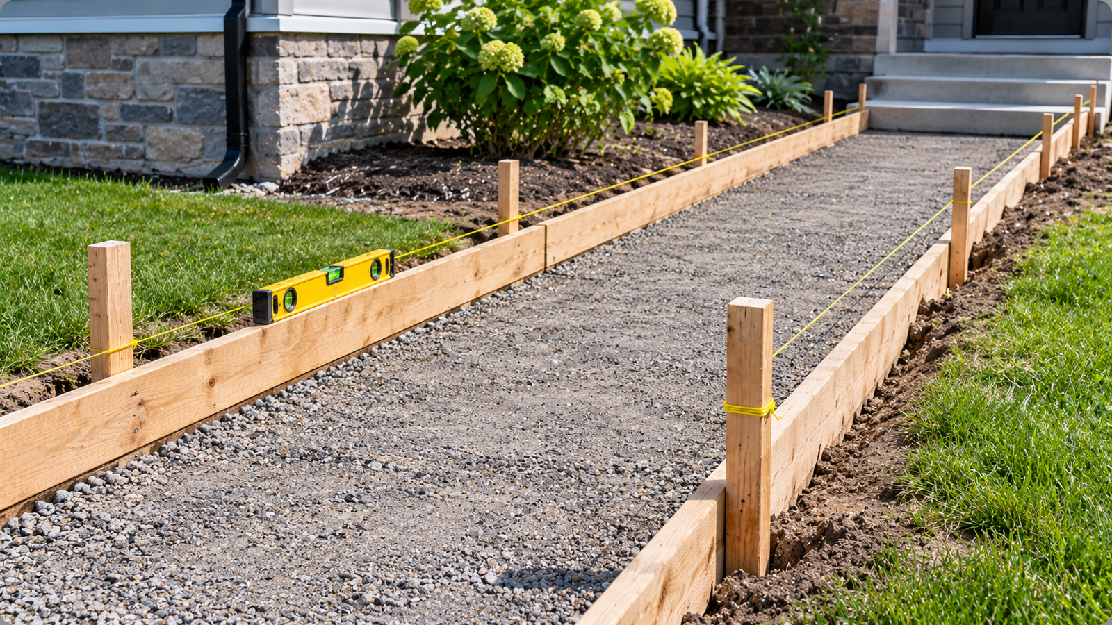
- Step 4: Set the First Form Board
- Step 5: Drive Stakes Without Moving the Form
- Step 6: Install the Opposite Form
- How Far Apart Should Sidewalk Form Stakes Be?
E. Set grade and cross slope
- What Is Running Slope vs. Cross Slope?
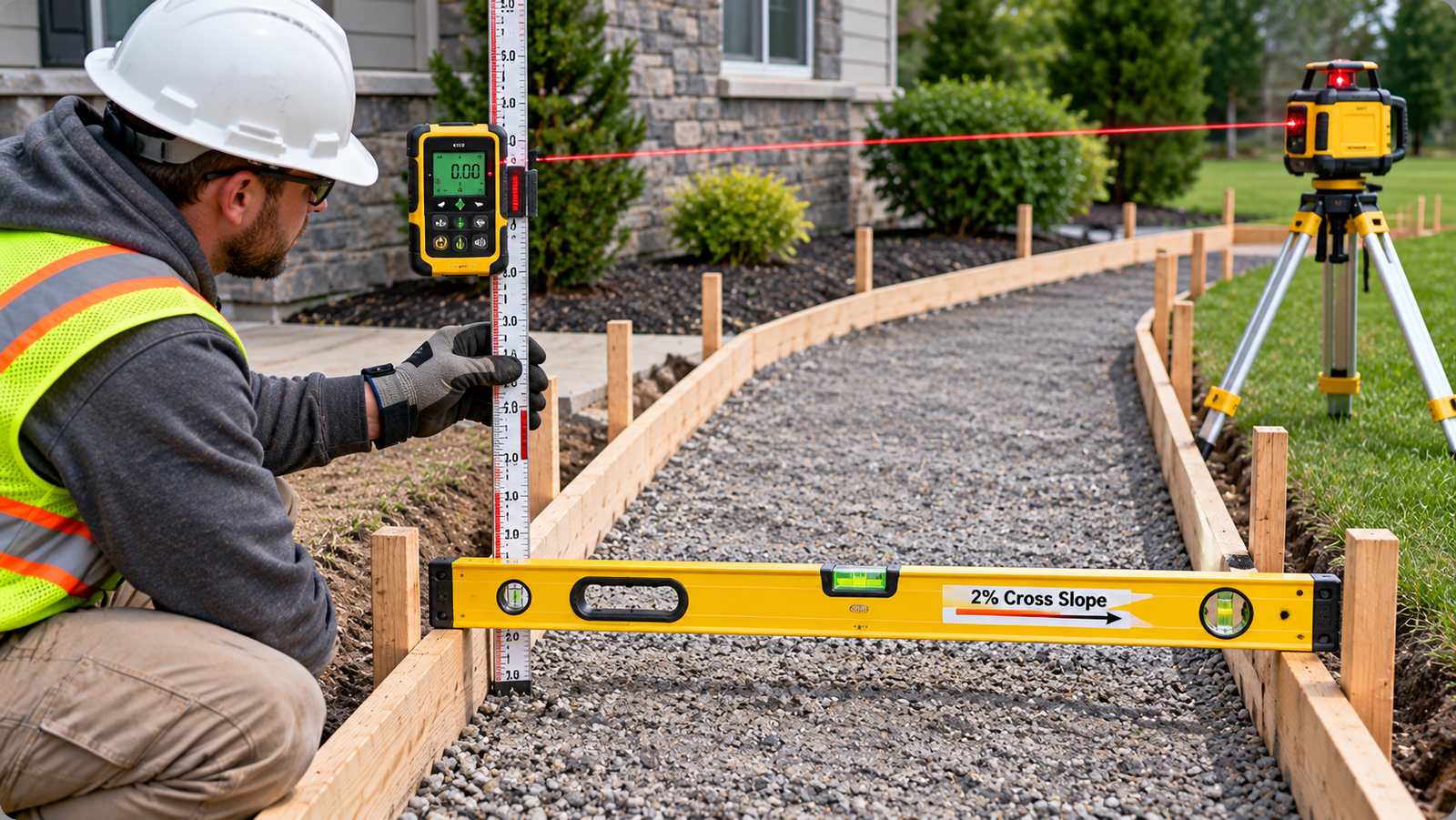
- How to Set Sidewalk Cross Slope With the Forms
- Which Direction Should a Sidewalk Slope?
- How to Check Form Elevations With a Laser or Stringline
F. Curves, transitions and adjacent concrete
- How to Form Curved Sidewalk Edges
- How to Form a Sidewalk Where It Meets Existing Concrete
- Isolation Joints at Walls, Steps and Other Fixed Objects
G. Plan joints and pour breaks
- Plan the Sidewalk Joint Layout Before the Pour
- Formed Joints vs. Tooled or Saw-Cut Joints
- How to Handle a Sidewalk Pour Stop
H. Inspect before concrete arrives
What Do Concrete Sidewalk Forms Actually Do?
Sidewalk forms do more than hold wet concrete in a neat line. They set the finished width, the edge depth and the top elevation, and they give the screed board a surface to ride on.
They also help create the running grade and cross slope. A form that is perfectly straight but set at the wrong height still produces a bad sidewalk.
ACI 347R describes formwork as the whole support system for fresh concrete, including the mold, supporting members, hardware and bracing. Its stated aim is correct dimensions, alignment and elevation within tolerance, with safe support of vertical and lateral loads.
A sidewalk is far simpler than structural wall formwork, but the principle carries over. The form must stay exactly where you put it when concrete pushes against it.
Forms do not decide the engineering design on their own. Width, thickness, slope and reinforcement come from the plan, the local standard or the accessibility rules that apply.
What Should You Check Before Building Sidewalk Forms?
Settle the constraints first, because they decide where the forms go and how high they sit.
- Property lines and any required setbacks
- Underground utilities, located through the national 811 call-before-you-dig service
- Permit requirements and the local sidewalk standard
- Existing elevations at doors, steps, driveways and garage aprons
- The drainage destination for water that leaves the walk
- Accessibility requirements, where they apply
If the walk connects to a public sidewalk or curb, the local public works detail should take precedence over generic DIY geometry.
Record the elevation of every fixed point the sidewalk must meet before you drive a single stake. Those numbers become your grade targets later.
How Wide and Thick Should the Sidewalk Be?
There is no single answer. Width and thickness depend on whether the walk is private or public, the loading, driveway crossings, the local code or specification, accessibility needs and the soil that supports it.
A private garden path, a public right-of-way sidewalk and an accessible route can have very different requirements. Use the plan or the local standard instead of a number from a forum post.
Once the dimensions are confirmed, the Sidewalk Calculator can check the concrete quantity, and the Concrete Slab Thickness Chart gives general context. Confirm any thickness against your local requirements before you build.
What Materials Do You Need for Sidewalk Forms?
Pick materials for the job in front of you. Board size should match the required edge depth and stiffness, not a habit of using 2×4s on every sidewalk.
A nominal 2×4 on edge stands about 3.5 in tall, and a nominal 2×6 stands about 5.5 in. The board must be at least as tall as the slab edge depth you need.
Fasten forms to stakes with screws or nails you can back out later, so the form can be adjusted during setup and removed cleanly afterward.
| Item | Purpose | Key caution |
|---|---|---|
| Form board | Defines the slab edge | Must remain straight and stable |
| Stakes | Hold the forms | Keep below the finishing path |
| Screws or nails | Fasten form to stake | Must allow adjustment |
| Stringline | Establishes alignment | Protect the reference from disturbance |
| Laser or level | Controls elevation | Check multiple stations |
| Tape measure | Width and layout | Measure between inside form faces |
| Straightedge | Checks grade and form alignment | Needs adequate length |
| Flexible form material | Forms curves | Needs closer support |
| Form release | Easier stripping where appropriate | Keep it off bond areas |
Marking paint, a spirit level, a hammer or drill and a handsaw round out the kit. If you need the amount of edge form material, the Concrete Formwork Calculator treats slab-edge forms separately from structural wall forms.
Step 1: Establish the Sidewalk Centerline or Edges
Two layout approaches work well. Choose the one that fits the site.
- Edge layout: mark both finished edges directly.
- Centerline layout: establish the centerline, then offset equal distances to each side.
Set your reference stakes and string outside the excavation zone so the layout survives digging. Mark the line on the ground with paint before you move the string.
Step 2: Check the Sidewalk Width
The finished width is the distance between the inside faces of the forms. That is the surface the concrete will actually fill.
Do not measure stake to stake or outside face to outside face. With nominal 2× lumber about 1.5 in thick, an outside-to-outside reading is roughly 3 in wider than the walk.
Check the width at both ends and at several points between them. Small drifts add up on a long sidewalk.
Step 3: Square Straight Walks and Corners
- Check rectangles with diagonals. Equal diagonals confirm square corners.
- Use the 3-4-5 triangle principle to set a right angle at a corner.
- Measure offsets from the building at several points, not only at the ends.
- Re-check alignment as you work so small errors do not accumulate.
A triangle with sides in a 3:4:5 ratio contains a right angle. Scale it up, such as 6-8-10 ft or 9-12-15 ft, for better accuracy over longer distances.
For free-running walks, align with the intended route. Do not force geometric squareness when the site conditions call for something else.
How to Lay Out Curved Concrete Sidewalks
Start with a garden hose or rope laid on the ground to preview the curve. Adjust it until the line looks smooth from several viewpoints, then mark it with paint.
Curves need a smooth, steady radius. Plan for a flexible form board, thin plywood or commercial flexible forms, and set stakes closer together than on straight runs.
Avoid segmented kinks unless they are part of the design. A visible flat spot in the form becomes a visible flat spot in the concrete edge.
Table 2 lists the measurements to establish before you finalize the layout.
| Measurement | Why it matters |
|---|---|
| Overall length | Concrete quantity and layout |
| Finished width | Walking surface |
| Finished elevation | Ties into the site |
| Slab thickness | Strength and material quantity |
| Running grade | Route elevation |
| Cross slope | Drainage and accessibility |
| Curve radius | Smooth form geometry |
| Existing concrete elevation | Avoids trip and transition problems |
| Joint locations | Crack control |
| Base or subgrade elevation | Maintains slab depth |
How Deep Should You Excavate for Sidewalk Forms?
Measure excavation depth downward from the proposed finished surface, which is the top of the forms.
Do not use a universal excavation depth. The result depends on the thickness the plan calls for and on whether a base is specified.
Example (numbers for demonstration only)
Suppose a plan calls for a 4 in slab over a 3 in base. Excavation depth = 4 + 3 = 7 in below the finished surface.
Your project may require different values, so take both thicknesses from your own documents.
Prepare and Compact the Subgrade
Forms set accurately on soft ground will not stay accurate. Prepare the support first, then set the forms.
- Remove topsoil and organic material.
- Dig out soft spots and replace them with suitable compacted material.
- Bring the subgrade to uniform, firm support.
- Compact any disturbed fill in thin layers.
ACI 332.1R-18, the residential concrete guide for one- and two-family dwellings, treats subgrade, forms, reinforcement, placement and curing as connected steps. See the ACI abstract for its scope.
For more on preparing the ground, read how to level ground for a concrete slab.
Does a Concrete Sidewalk Need a Gravel Base?
Sometimes, and sometimes not. A granular base can give uniform support, help with drainage, correct small grade errors and provide firm access for construction.
In other conditions a light-duty slab can perform on properly prepared subgrade. Soft, wet or poorly draining soils are the cases where a base is more likely to be needed.
Do Not Treat a Base Depth as Universal
A 4 in gravel base is not mandatory everywhere. Follow your local design, soil conditions and project requirements.
For drainage context around concrete flatwork, see concrete driveway drainage.
Set the Base to the Correct Elevation Before Final Forming
The forms define the top of the slab, while the subgrade or base defines the bottom. Both must be right for the slab to have the intended thickness.
Cut a scrap board to the planned slab thickness and use it as a depth gauge. Drag it between the forms to find high spots and low spots before concrete arrives.
Fix thin areas now by trimming the base. Fix deep areas by adding and compacting material, not by loose fill that will settle.
Step 4: Set the First Form Board
Start with the side that matters most. That might be the building side, the property-line side, the curb side or whichever edge is fixed by existing construction.
Set the board to the approximate line, elevation and running grade. Sight along the top edge to confirm it is straight.
Do not fully brace the form yet. Check alignment and elevation first, because a stake driven too early locks in any error.
Step 5: Drive Stakes Without Moving the Form
Stakes must resist the sideways force of the concrete and the push of the screed. Drive them outside the form, not inside the concrete.
- Set stake tops below the top of the form so they never block the screed.
- Drive stakes plumb and firm, with the board held in position by hand.
- Fasten the form to the stake only after alignment and elevation are confirmed.
- Pre-drill near board ends if the wood tends to split.
If a stake pulls the form out of line as it is fastened, back it off and re-check. A form that looks right but is under tension tends to spring back during the pour.
Step 6: Install the Opposite Form
Set the second form from the first, not by eye. You need three controls: the width between inside faces, the elevation difference and the cross-slope target.
Measure the width at each stake location. Then set the second board lower or higher than the first by the planned drop, using a level, a laser receiver or a straight board with a shim.
Independent eyeballing of both sides is unreliable, because small errors on each side can combine into a wrong slope.
How Far Apart Should Sidewalk Form Stakes Be?
There is no universal spacing. Many guides say a stake every few feet, but the right support depends on board stiffness, soil firmness, form height, curve radius and how hard the screed will push.
ACI 347R points to the stronger principle: formwork should be braced and anchored enough to remain stable under the loads placed on it.
Use a field test. Push the form sideways by hand, then run a screed board across it. If the form moves, bows or rolls, add support.
- Add stakes at curves and tight transitions.
- Add support at board joints and form ends.
- Add support over low spots and weak ground.
What Is Running Slope vs. Cross Slope?
Running slope is the slope along the direction of travel. Cross slope is the slope perpendicular to travel, from one edge of the walk to the other.
Where accessibility rules apply, the U.S. Access Board sets the running slope of walking surfaces at no steeper than 1:20 (5%) and the cross slope at no steeper than 1:48, which is about 2.1% (ADA Standards, Chapter 4).
For pedestrian access routes in the public right-of-way, PROWAG also limits cross slope to 1:48 (2.1%) outside crosswalks. Its running grade limit is 1:20 (5%), with an exception where the adjacent street grade is steeper.
| Slope | Drop per foot | Drop across 4 ft |
|---|---|---|
| 1% | 0.12 in | 0.48 in |
| 1.5% | 0.18 in | 0.72 in |
| 2% | 0.24 in | 0.96 in |
| 1:48 (about 2.1%) | 0.25 in | 1.00 in |
To convert elevations to grade, the Elevation Grade Calculator can help.
How to Set Sidewalk Cross Slope With the Forms
Build the cross slope into the forms by setting one edge lower than the other. The drop equals the width multiplied by the slope.
Example (for illustration only): 4 ft wide walk at 2% cross slope
Drop = 4 ft × 0.02 = 0.08 ft
Drop in inches = 0.08 × 12 = 0.96 in
Accessible routes use a maximum cross slope of 1:48 (about 2.1%), and local or public specifications control. The 2% figure is a geometry example, not a recommendation.
Sidewalk forms control both slab edges and the finished cross slope, so their top elevations must be set together.
Which Direction Should a Sidewalk Slope?
Slope the surface toward a safe drainage destination. That usually means away from buildings and retaining walls, and away from places where water would collect.
Do not reduce this to a rule such as always slope 2% away from the house. Accessibility limits and public right-of-way constraints can restrict how much cross slope you can use.
On a walk beside a building, check where the water will actually go once it leaves the edge. A drainage plan matters as much as the slope number.
Forms should create a uniform intended cross slope rather than an accidental low spot or drainage toward the building.
How to Check Form Elevations With a Laser or Stringline
Several tools can verify form elevation. Each has strengths.
- Laser level: fast and accurate over longer runs, used with a receiver on a rod.
- Builder’s level: reliable, but needs a second person to read the rod.
- Stringline: good for straightness and for checking height between stations.
- Long straightedge plus level: practical for short sections and for checking across the forms.
Record control elevations at several stations along a long sidewalk. Checking only the two ends can miss a dip in the middle.
Public agencies treat this as a construction-control step. One FHWA pavement inspection checklist asks whether the grade was checked by scratch board or stringline between the forms before the pour.
How to Form Curved Sidewalk Edges
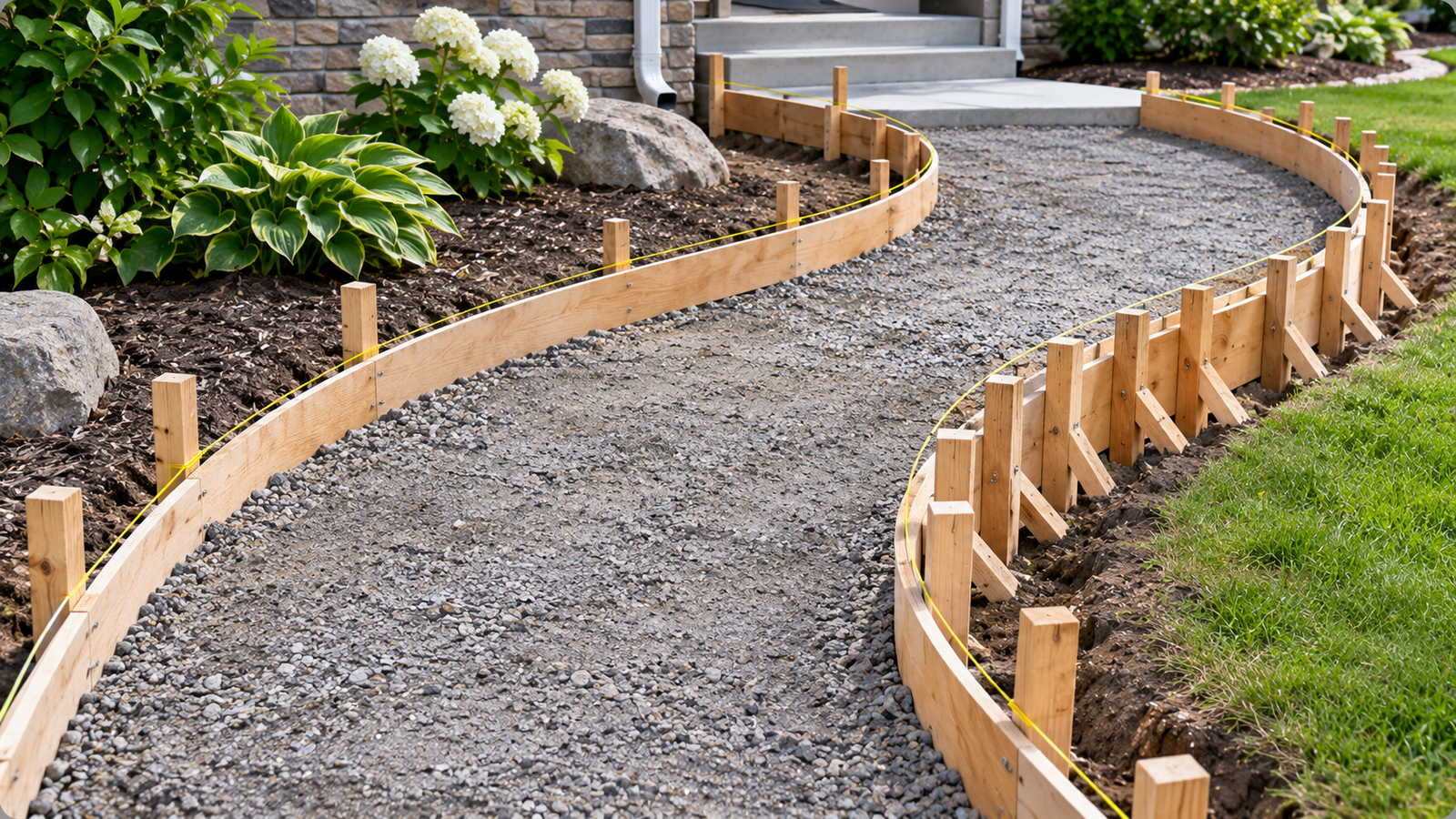
Use flexible form material, keep the curve smooth and continuous, and stake it more closely than a straight run. Check both edges to keep the width consistent.
The inside and outside edges of a curve have different radii, so they have different lengths. Cut and plan form material for each edge separately.
Example (illustrative geometry): 90 degree turn, 4 ft wide, 10 ft centerline radius
Inside radius = 10 − 2 = 8 ft, outside radius = 10 + 2 = 12 ft.
Arc length = (π ÷ 2) × radius. Inside = 12.6 ft, centerline = 15.7 ft, outside = 18.8 ft.
Tighter radii need more support and more careful bending. Sight along the curve from a low angle to catch flat spots before you fasten the last stake.
How to Form a Sidewalk Where It Meets Existing Concrete
Existing driveways, porches, steps, garage aprons and older sidewalks all affect form elevation. Match their elevations at the connection before you set the rest.
Even a small vertical offset is a trip hazard. Check the transition with a straightedge across the joint line before the pour.
The interface may need an isolation joint or a construction joint, depending on the design. NRMCA CIP 6 calls for isolation joints between driveways and sidewalks, so decide the detail before concrete is placed.
Isolation Joints at Walls, Steps and Other Fixed Objects
An isolation joint separates the sidewalk from a restrained element so each part can move independently. It limits cracking where movement would otherwise be blocked.
NRMCA describes isolation joints between slabs and walls, footings, columns, stairs, garage slabs, light poles and driveways. It names premolded joint filler, such as asphalt-impregnated fiber sheeting or compressible foam strips, as suitable materials.
Position the isolation material before the pour, flush with the intended top of the slab. Do not confuse it with a contraction joint, which is a planned weak plane within the slab.
Plan the Sidewalk Joint Layout Before the Pour
NRMCA gives these guidelines for contraction joints in slabs on grade:
- Maximum spacing of 24 to 36 times the slab thickness.
- A limit of about 15 ft, whatever the thickness.
- Panels that are square or nearly square, with length no more than about 1.5 times the width.
- No L-shaped panels.
On a narrow sidewalk, the panel shape rule usually controls. A 4 ft wide walk with panels no longer than 1.5 times the width suggests joints roughly every 4 to 6 ft.
That is an application of NRMCA’s geometry, not a national code requirement. Follow the project or local requirement where one exists.
Plan contraction joints and isolation points before placement so the sidewalk forms, finishing operation and joint layout work together.
For more detail, see concrete control joints and the Expansion Joint Spacing Chart.
Formed Joints vs. Tooled or Saw-Cut Joints
Contraction joints can be created several ways. NRMCA lists forming, tooling, sawing and joint formers.
- Preformed strips: inserted into the surface to the required depth before finishing.
- Tooled joints: cut early in finishing and run again later so the groove does not bond.
- Saw-cut joints: cut after the concrete has set enough to avoid raveling.
NRMCA recommends a groove at least one quarter of the slab thickness deep, and not less than 1 in.
Conventional saw cuts are generally run within 4 to 12 hours of finishing, and early-entry dry cuts about 1 to 4 hours after finishing, depending on how the concrete sets.
Side forms establish the slab edges. Interior contraction joints do not require separate wood divider forms. If the slab contains wire mesh, NRMCA advises discontinuing it across contraction joints.
How to Handle a Sidewalk Pour Stop
A pour stop creates a construction joint, where one placement ends and the next begins. Plan its location before the pour, ideally at a planned contraction joint position.
- Use a full-depth end form, called a bulkhead, set square to the walk.
- Keep it aligned with the side forms and at the correct top elevation.
- Coordinate the joint with the contraction-joint pattern.
- Add reinforcement or dowels only if the project documents call for them.
NRMCA describes a beveled key for slabs at least 5 in thick and dowels for heavy loads. Do not add dowel requirements to a residential walk on your own.
| Joint | Main purpose | Typical location |
|---|---|---|
| Contraction / control | Predetermine where shrinkage cracks form | Across the sidewalk panels |
| Isolation | Separate the slab from a restrained object | Walls, steps, fixed structures |
| Construction | End one placement and start another | Planned pour stop |
| Existing pavement interface | Allow and detail the transition | Driveway or existing slab |
Sidewalk Formwork Pre-Pour Checklist
Inspect everything before concrete arrives. Once the truck is on site, changes are expensive and rushed.
Public agencies build this check into their field reviews. FHWA’s structural concrete review includes confirming that forms are tight and that chips, dirt and sawdust are cleaned out before placement.
The pavement review also asks whether fixed forms are cleaned, oiled and secured against movement. Use the same mindset on a small sidewalk.
- Alignment and inside width
- Finished elevations, running grade and cross slope
- Base depth and compaction
- Curves, stake stability and form joints
- Isolation material and the contraction-joint layout
- Reinforcement, sleeves or embeds if specified
- Concrete quantity and access for placing and screeding
Confirm the quantity with the Concrete Slab Calculator or the concrete material takeoff method, and plan the delivery with the Ready Mix Truck Calculator. See how to read a ready-mix delivery ticket for checking the load.
Table 5 lists the most common sidewalk formwork mistakes and how to avoid them.
| Mistake | What happens | Better approach |
|---|---|---|
| Forms set on soft soil | Edge drops or moves | Compact support first |
| Both form tops made level | Water may pond | Set an intentional cross slope |
| Stakes too weak or too far apart | Forms bow outward | Add support based on stiffness |
| Width measured outside the forms | Sidewalk too narrow or wide | Measure finished inside faces |
| Curve under-staked | Flat spots and kinks | Add closer stakes |
| Joint plan ignored | Random cracking | Plan joints before the pour |
| Form top elevation not checked | Uneven sidewalk | Laser or string at multiple stations |
| Thickening not matched by excavation | Slab ends too thin | Verify base-to-form depth |
| Existing concrete not isolated where required | Restrained cracking | Install the correct joint detail |
| Screws or stakes project above the edge | Screeding obstruction | Keep the finishing path clear |
Run the final inspection in Table 6 before you call for concrete.
| Check | Ready? |
|---|---|
| Layout matches plan and property constraints | ☐ |
| Inside width correct | ☐ |
| Forms straight or smoothly curved | ☐ |
| Finished elevation checked | ☐ |
| Running grade checked | ☐ |
| Cross slope checked | ☐ |
| Subgrade compacted | ☐ |
| Base condition verified | ☐ |
| Slab depth checked between form and base | ☐ |
| Stakes and forms do not move under pressure | ☐ |
| Isolation joints installed where required | ☐ |
| Contraction-joint layout marked | ☐ |
| Reinforcement and embeds installed if specified | ☐ |
| Concrete quantity confirmed | ☐ |
| Placement and screed access clear | ☐ |
Concrete Sidewalk Form FAQs
What boards should I use for sidewalk forms?
Use straight, dry boards or purpose-made forms that are at least as tall as the slab edge depth and stiff enough to stay straight under load. A nominal 2×4 on edge is about 3.5 in tall, and a nominal 2×6 is about 5.5 in.
Can I use 2×4s for sidewalk forms?
Yes, if the board is straight, well supported and tall enough for the required edge depth. A nominal 2×4 is about 3.5 in tall, so a deeper slab or thickened edge needs a taller board.
How far apart should form stakes be?
There is no universal spacing. It depends on board stiffness, soil, form height, curves and how the concrete is placed and screeded. Test by pushing the form and running a screed across it, and add stakes if it moves.
Should sidewalk forms be level?
Not necessarily. Running grade follows the route, and cross slope is built in on purpose so water drains. Where accessibility rules apply, the cross slope may not be steeper than 1:48 (about 2.1%).
How do I create cross slope?
Set the high-side form first, then set the low-side form lower by the planned drop, which equals width times slope. For example, a 4 ft wide walk at 2% needs about 0.96 in of drop.
How do I form a curved sidewalk?
Lay out a smooth radius with a hose or rope, use flexible form material, and stake it more closely than a straight run. Check both edges so the width stays consistent.
Do I need a gravel base?
Not always. A base can help with support and drainage, but some light-duty slabs perform on well-prepared subgrade. Follow your local design, soil conditions and project requirements.
When do I use an isolation joint?
Use one where the sidewalk meets a restrained element such as a wall, footing, column, step, garage slab or driveway, so each part can move independently.
How far apart should sidewalk control joints be?
NRMCA recommends a maximum of 24 to 36 times the slab thickness, a limit of about 15 ft, and panels that are square or nearly square with length no more than about 1.5 times the width. A narrow walk often needs closer joints.
When can sidewalk side forms be removed?
There is no single hour count. It depends on temperature, the mixture, edge strength and the project specification. Remove forms only when the edges are strong enough not to be damaged.
For timing after the pour, see when you can walk on concrete and the Concrete Curing Time Chart.
Conclusion
Good sidewalk forms hold the line, width and elevation while concrete is placed. Set support first, build the cross slope in deliberately, brace the forms so they cannot move, and plan the joints before the pour.
Confirm your concrete quantity before ordering.
Open the Sidewalk Calculator