
Clearance Hole Size Chart – Close, Normal, Loose & Metric Fit
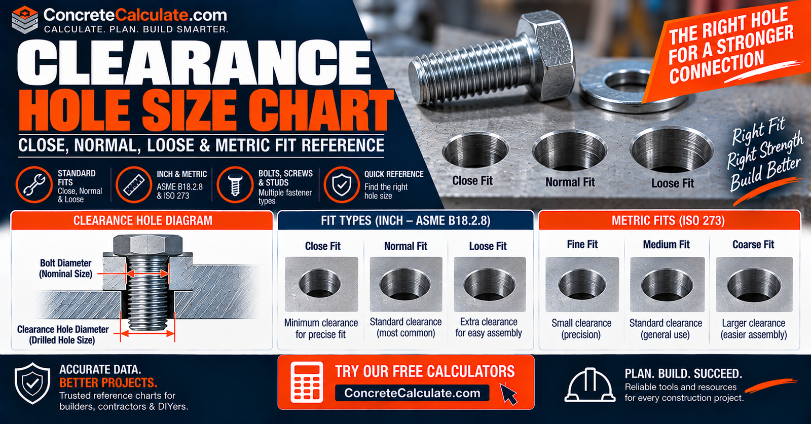
Clearance Hole Size Chart
Close, Normal, Loose & Metric Fit
General-purpose clearance hole diameters for bolts, screws, and studs under ASME B18.2.8 inch close, normal, and loose fit classes and ISO 273 metric fine, medium, and coarse series, plus the critical distinction from tapped holes, pilot holes, and structural bolt holes.
 Reviewed by Muhammad Ramzan Babar, PhD Researcher (Plasma Physics) & Calculator Developer, View Profile
A clearance hole is intentionally larger than the fastener, and the correct amount depends on the required fit
There is no single universal “bolt plus 1/16 in.” rule. For U.S. inch and general-purpose metric fasteners, ASME B18.2.8 divides clearance into close, normal, and loose fit categories. For ISO metric work, ISO 273 uses fine, medium, and coarse series. These are general-purpose clearance-hole sizes; structural-steel bolt holes, tapped holes, wood-bolt holes, and concrete-anchor drill holes use separate rules covered on other pages.
Clearance Hole Size Chart, Quick Reference
Two separate primary charts, not one mixed chart, since inch and metric systems use different fit terminology.
Inch Clearance Hole Size Chart
| Fastener Size | Close Clearance | Normal Clearance | Loose Clearance |
|---|---|---|---|
| #6 | 0.150 | 0.166 | 0.180 |
| #10 | 0.219 | 0.234 | 0.250 |
| 1/4 in. | 0.281 | 0.302 | 0.332 |
| 3/8 in. | 0.406 | 0.422 | 0.484 |
| 1/2 in. | 0.531 | 0.562 | 0.625 |
| 5/8 in. | 0.656 | 0.688 | 0.750 |
| 3/4 in. | 0.781 | 0.812 | 0.906 |
| 1 in. | 1.031 | 1.062 | 1.156 |
Metric Clearance Hole Size Chart
| Fastener | Fine | Medium | Coarse |
|---|---|---|---|
| M3 | 3.2 mm | 3.4 mm | 3.6 mm |
| M4 | 4.3 mm | 4.5 mm | 4.8 mm |
| M5 | 5.3 mm | 5.5 mm | 5.8 mm |
| M6 | 6.4 mm | 6.6 mm | 7.0 mm |
| M8 | 8.4 mm | 9.0 mm | 10.0 mm |
| M10 | 10.5 mm | 11.0 mm | 12.0 mm |
| M12 | 13.0 mm | 13.5 mm | 14.5 mm |
| M16 | 17.0 mm | 17.5 mm | 18.5 mm |
| M20 | 21.0 mm | 22.0 mm | 24.0 mm |
Important Scope Note
These are general-purpose clearance-hole sizes. Structural-steel bolt holes, tapped holes, wood-bolt holes, and concrete-anchor drill holes use separate rules covered on other pages of this site.
What Is a Clearance Hole?
An unthreaded hole intentionally larger than the fastener.
A clearance hole is an unthreaded hole intentionally larger than the fastener so the bolt, screw, or stud can pass through freely. Its purpose is to allow assembly, positional tolerance, alignment, and installation clearance. It is not intended to engage the external fastener thread.
Clearance Hole vs Fastener Diameter
The fundamental relationship on this page.
For a nominal fastener diameter d, the clearance-hole diameter Dh must be greater than d. The difference, C = Dh minus d, represents total diametral clearance. Clearance is deliberately added; the hole should not normally equal nominal fastener diameter.
Radial vs Diametral Clearance
A useful technical distinction that adds depth without becoming overly theoretical.
Example: M10 Bolt in an 11-mm Hole
Why Clearance Hole Size Matters
Affects far more than just whether the bolt fits.
Clearance affects assembly speed, alignment tolerance, positioning accuracy, movement or play, bearing area, washer requirements, edge distance, and fabrication tolerance. Too small a hole causes difficult assembly, binding, or thread damage. Too large a hole causes unnecessary movement, lower positional accuracy, and potential bearing or detailing concerns.
Close-Fit Clearance Holes
ASME B18.2.8 recognizes a close class of clearing.
Use a close fit when alignment needs to be tighter, positional play should be minimized, or parts are accurately manufactured and aligned. Close fit still means clearance, not an interference or press fit.
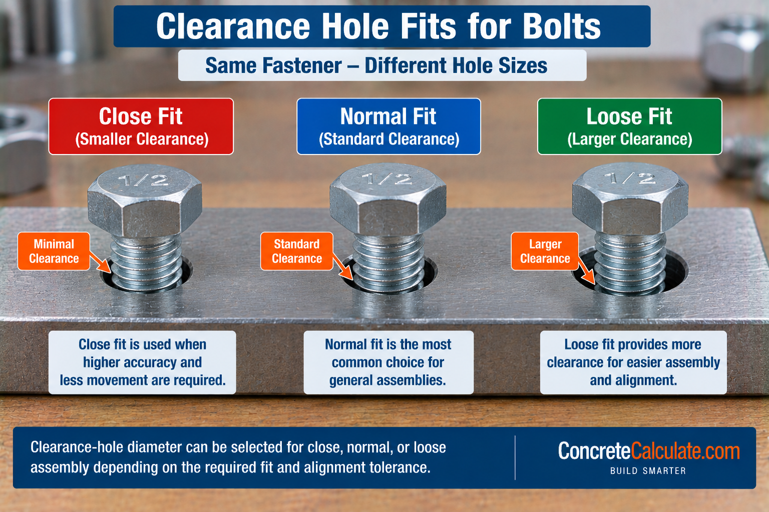
Normal-Fit Clearance Holes
The central general-purpose category.
Use normal fit where ordinary assembly is required, manufacturing tolerances need accommodation, and no unusually tight or loose fit is necessary. This is typically the most common default, though it is not automatically correct for every application.
Loose-Fit Clearance Holes
Provides more installation room.
Loose clearing is useful when alignment is less controlled or assembly ease is more important, and where fabrication variation is larger. Larger holes can have consequences for positioning, washer bearing, and load-bearing assemblies.
Close vs Normal vs Loose Clearance
A direct comparison of the three ASME classes.
| Fit | Relative Hole Size | Assembly Ease | Positional Play | Typical Context |
|---|---|---|---|---|
| Close | Smallest | Lower | Lowest | Accurate alignment |
| Normal | Medium | Good | Moderate | General assembly |
| Loose | Largest | Highest | Highest | Generous assembly tolerance |
ASME B18.2.8 Clearance Hole Standard
The main U.S. authority section.
ASME states that B18.2.8 covers recommended clearance holes for bolts, screws, and studs, inch fasteners from #0 through 1.5 in., and metric fasteners from M1.6 through M100, in three classes: close, normal, and loose. The standard is under Stabilized Maintenance, but ASME explicitly states the version remains in effect.
Machine Screw Clearance Hole Chart
A focused small-fastener chart for homeowner, shop, and fabrication use.
| Screw Size | Nominal Major Diameter | Close Hole | Normal Hole | Loose Hole |
|---|---|---|---|---|
| #0 | 0.060 | 0.067 | 0.073 | 0.086 |
| #4 | 0.112 | 0.120 | 0.136 | 0.150 |
| #6 | 0.138 | 0.150 | 0.166 | 0.180 |
| #8 | 0.164 | 0.180 | 0.196 | 0.213 |
| #10 | 0.190 | 0.219 | 0.234 | 0.250 |
| #12 | 0.216 | 0.242 | 0.260 | 0.281 |
For machine screw thread designations, see the Machine Screw Size Chart.
Fractional-Inch Bolt Clearance Hole Chart
Larger fractional fasteners separated from machine screws.
| Bolt Size | Close | Normal | Loose |
|---|---|---|---|
| 1/4 | 0.281 | 0.302 | 0.332 |
| 5/16 | 0.344 | 0.359 | 0.397 |
| 3/8 | 0.406 | 0.422 | 0.484 |
| 7/16 | 0.469 | 0.484 | 0.531 |
| 1/2 | 0.531 | 0.562 | 0.625 |
| 9/16 | 0.594 | 0.625 | 0.688 |
| 5/8 | 0.656 | 0.688 | 0.750 |
| 3/4 | 0.781 | 0.812 | 0.906 |
| 7/8 | 0.906 | 0.938 | 1.000 |
| 1 | 1.031 | 1.062 | 1.156 |
Metric Fine Clearance Hole Chart
The smallest general-purpose ISO clearance series.
| Metric Fastener | Fine Clearance Hole | Diametral Clearance |
|---|---|---|
| M4 | 4.3 mm | 0.3 mm |
| M6 | 6.4 mm | 0.4 mm |
| M8 | 8.4 mm | 0.4 mm |
| M10 | 10.5 mm | 0.5 mm |
| M12 | 13.0 mm | 1.0 mm |
ISO 273 specifically recognizes fine, medium, and coarse series.
Metric Medium Clearance Hole Chart
Likely the most-used ISO chart in practice.
| Metric Fastener | Medium Clearance Hole |
|---|---|
| M4 | 4.5 mm |
| M5 | 5.5 mm |
| M6 | 6.6 mm |
| M8 | 9.0 mm |
| M10 | 11.0 mm |
| M12 | 13.5 mm |
| M16 | 17.5 mm |
| M20 | 22.0 mm |
Medium is a recognized standard series, not automatically the correct choice for every assembly.
Metric Coarse Clearance Hole Chart
Significantly more assembly allowance.
| Metric Fastener | Coarse Hole | Added Clearance |
|---|---|---|
| M6 | 7.0 mm | 1.0 mm |
| M8 | 10.0 mm | 2.0 mm |
| M10 | 12.0 mm | 2.0 mm |
| M12 | 14.5 mm | 2.5 mm |
| M16 | 18.5 mm | 2.5 mm |
| M20 | 24.0 mm | 4.0 mm |
ISO 273 Metric Clearance Hole Standard
The metric authority section.
ISO 273:1979 remains current after confirmation in 2024. It covers general-purpose clearance holes, uses fine, medium, and coarse series, and covers thread diameters from 1 mm to 150 mm. Importantly, ISO 273 also states that holes for special applications should be selected based on design requirements, meaning these tabulated series are general-purpose starting points, not a mandatory value for every situation.
Inch vs Metric Clearance Hole Systems
Conceptually similar categories, but separate standards.
| Feature | ASME Inch/Metric System | ISO Metric System |
|---|---|---|
| Standard | ASME B18.2.8 | ISO 273 |
| Fit terms | Close / Normal / Loose | Fine / Medium / Coarse |
| Inch sizes | Yes | No |
| Metric sizes | Yes | Yes |
Do not assume close equals fine, normal equals medium, or loose equals coarse as a strict one-to-one dimensional equivalence unless values are checked size by size; they are conceptually similar categories, but the standards remain separate.
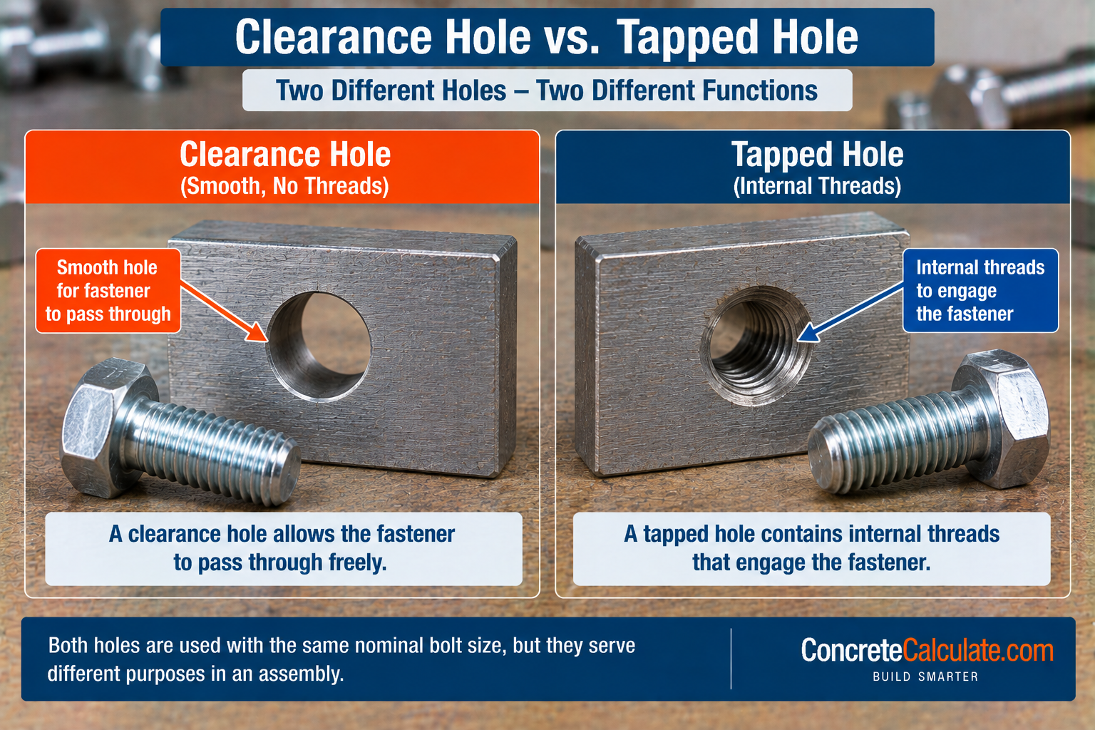
Clearance Hole vs Tapped Hole
One of the most important distinctions on this page.
| Type | Description |
|---|---|
| Clearance Hole | Larger than bolt major diameter |
| Tapped Hole | Drilled smaller than major diameter, then internally threaded |
An M8 coarse tap drill measures approximately 6.8 mm, while a general M8 clearance hole ranges from about 8.4 to 10 mm depending on fit. That large difference makes the concept clear. See the Tap Drill Chart for complete tapped-hole sizing.
Clearance Hole vs Tap Drill Size
An explicit side-by-side comparison.
| Fastener | Tap Drill | Clearance Hole (Medium) | Purpose |
|---|---|---|---|
| M6 | ~5.0 mm | 6.6 mm | Threaded vs pass-through |
| M8 | ~6.8 mm | 9.0 mm | Threaded vs pass-through |
| M10 | ~8.5 mm | 11.0 mm | Threaded vs pass-through |
Never use a tap-drill chart to select a pass-through clearance hole; the two hole types serve opposite functions.
Clearance Hole vs Pilot Hole
Another common confusion.
| Type | Function |
|---|---|
| Pilot Hole | Guides a drill or screw, or controls engagement in materials such as wood |
| Clearance Hole | Allows the fastener shank or thread to pass freely |
Pilot-hole diameter depends on material, screw type, and thread geometry. See the Pilot Hole Size Chart for material-specific pilot-hole data.
Clearance Hole vs Structural Bolt Hole
Essential now that this site has both a general clearance page and a structural page.
| Category | Description |
|---|---|
| General Clearance Hole | ASME/ISO fit-based machining and fabrication reference (close/normal/loose or fine/medium/coarse) |
| Structural Steel Hole | AISC/RCSC connection-design category: standard, oversized, short slot, or long slot |
AISC explicitly distinguishes these structural categories and states that holes exceeding a category limit must be treated as the next larger category. See the Bolt Hole Size Chart for the complete structural-steel hole reference.
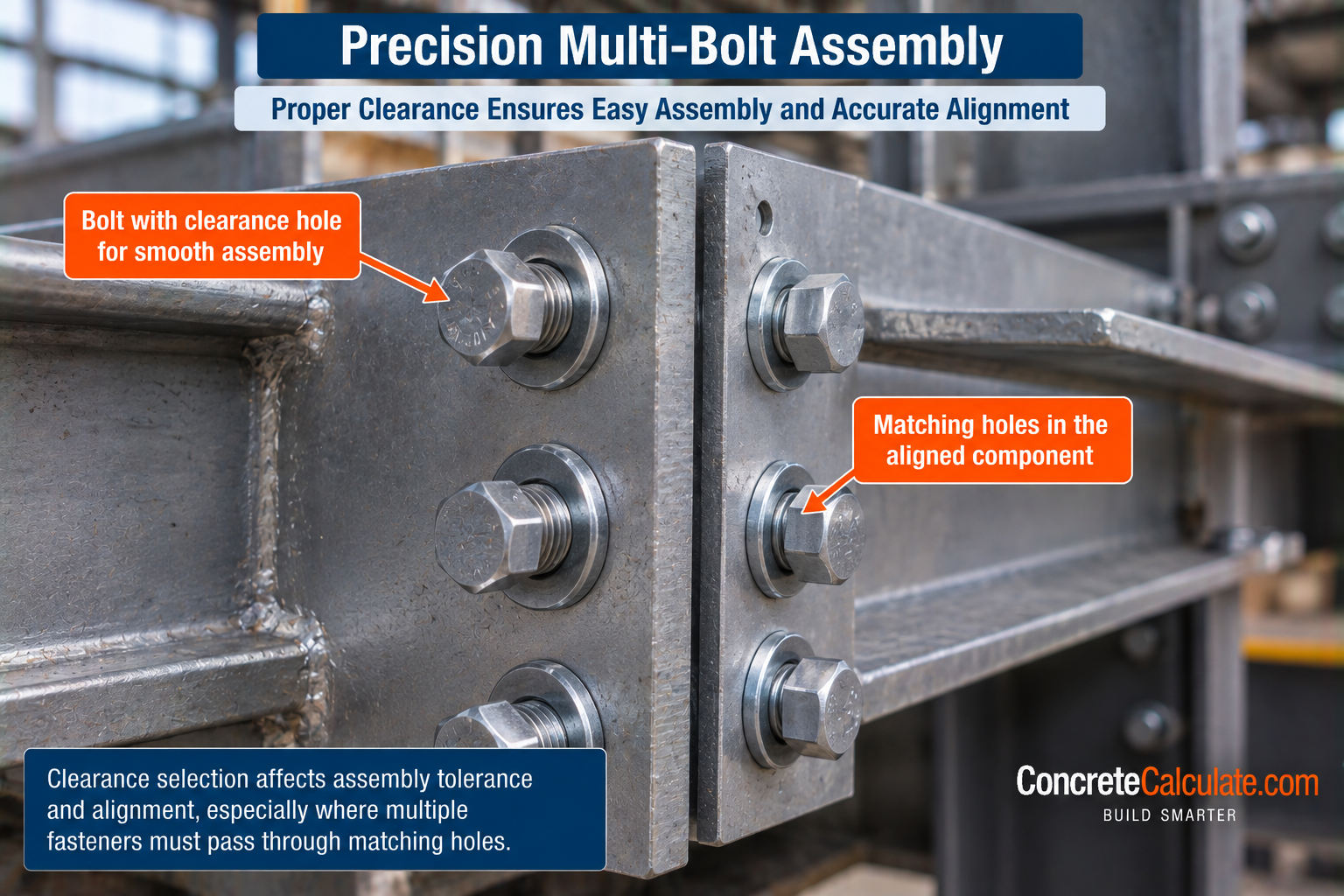
Why Structural Hole Tables Should Not Be Mixed Into This Chart
Structural-hole geometry has consequences beyond simple clearance.
Structural-hole geometry affects slip-critical design, bearing, washer requirements, net-section behavior, edge distance, and installation. AISC’s current standard family includes ANSI/AISC 360-22, while RCSC’s 2025 Specification for Structural Joints Using High-Strength Bolts is the current governing document for bolt installation and joint requirements. Keep only a brief structural cross-reference here and send detailed intent to the Bolt Hole Size Chart.
Clearance Hole Size and Washer Selection
A larger clearance hole can reduce bearing area beneath the bolt head or nut.
Washer selection may depend on hole size, bolt diameter, material, and whether the application is structural or nonstructural. See the Washer Size Chart for dimensional data; structural washer requirements are covered specifically on the Bolt Hole Size Chart rather than duplicated here.
Clearance Hole Size and Fastener Head Size
A hole can be acceptable for the shank but problematic for the head.
Beyond the shank clearance itself, check head bearing diameter, washer fit, and countersink or counterbore geometry if applicable. See the Hex Bolt Size Chart for head dimensional data.
Clearance Hole Size and Positional Tolerance
One of the main engineering reasons for different fit classes.
Larger clearance can compensate for hole-location variation, dimensional stackup, part misalignment, and multi-fastener assemblies. Excessive clearance, however, can reduce positional control, which is why fit selection should match the actual assembly requirement rather than defaulting to the largest available option.
Clearance Holes in Thin Sheet and Thick Plate
Material thickness introduces its own practical considerations.
In thin sheet metal, consider bearing around the hole, deformation, washer use, burrs, and hole quality; do not prescribe a universal enlargement, but pay attention to edge distance, local bearing, and larger washers or flanges where needed. In thick plate, consider drill wander, reaming, hole straightness, and alignment between stacked parts; for precision assemblies, achieving a close fit through thick stacked material can be harder without controlled machining.
Drilled, Punched, and Reamed Clearance Holes
General-purpose fabrication methods.
| Method | Description |
|---|---|
| Drilled | Conventional or CNC drilled |
| Punched | High-production sheet or plate fabrication |
| Reamed | Used to improve size, alignment, or finish after drilling |
Structural-specific fabrication details, such as reaming limits for AISC/RCSC connections, are covered on the Bolt Hole Size Chart.
Clearance Hole Manufacturing Tolerances
The nominal chart value is not the same as allowable fabrication tolerance.
Practical fabrication also involves actual drilled diameter, tool wear, hole roundness, positional tolerance, and burrs. A clearance-hole chart gives the nominal target size; drawing tolerances still need to be specified separately when fit is critical.
Coated and Galvanized Fastener Clearance
Coatings can affect actual external diameter and assembly clearance.
Zinc plating and hot-dip galvanizing can affect actual external diameter, assembly clearance, and friction. Do not automatically oversize holes without the applicable specification. AISC specifically states that galvanized structural bolts or members are not permitted to use holes larger than the specified structural-hole limits merely because they are galvanized, a useful caution even on this general clearance page.
Special-Application Clearance Holes
ISO 273 itself acknowledges limits to the general-purpose series.
ISO 273 states that holes for special applications should be selected based on design requirements rather than the general fine, medium, or coarse series. This means unusual assembly conditions, high-precision alignment, or specific project specifications may call for a clearance value outside these general tables entirely.
How to Choose the Correct Clearance Hole Size
The practical decision workflow.
Clearance Hole Selection Workflow
Common Mistakes and Chart Limitations
Drilling exactly nominal bolt diameter for a free-passing bolt
A true clearance hole must always be larger than the bolt.
Using “bolt plus 1/16 in.” as a universal rule
The correct allowance depends on fit class and fastener size.
Confusing clearance hole with tapped hole
These serve entirely different, opposite functions.
Using tap-drill diameter as clearance diameter
Tap drills are significantly smaller than clearance holes.
Confusing clearance hole and pilot hole
Pilot holes guide engagement into material; clearance holes allow free passage.
Treating close/normal/loose as structural hole categories
These are general ASME/ISO fit classes, not AISC structural categories.
Treating ISO fine/medium/coarse as AISC standard/oversized/slotted
These belong to entirely separate hole-classification systems.
Mixing ASME and ISO numerical values without checking
Similar-sounding fit categories can have different exact dimensions.
Assuming M12 always uses one clearance-hole size
Fine, medium, and coarse fits all produce different valid hole diameters.
Ignoring positional tolerance
Multi-fastener assemblies often need extra clearance to accommodate stackup.
Ignoring washer/head bearing
A shank-compatible hole may still be too large for adequate head bearing.
Assuming galvanizing automatically permits a larger structural hole
AISC does not allow enlarging structural holes solely due to galvanizing.
Using structural AISC dimensions for ordinary machine assemblies without need
General ASME/ISO clearance is typically the correct reference for non-structural work.
Applying general clearance charts to concrete anchors or wood pilot holes
These applications follow entirely separate, product or material-specific rules.
Read before finalizing a clearance hole selection
A clearance hole is larger than the nominal fastener diameter, and there is no single universal clearance amount. ASME uses close, normal, and loose categories, while ISO uses fine, medium, and coarse series, and special applications may require different dimensions entirely. Structural steel uses a separate AISC/RCSC system, and tap drill and pilot-hole sizes are different from clearance holes. Material thickness and positional tolerance matter, and head and washer bearing must still be checked. Fabrication tolerances are separate from nominal hole diameter, and concrete-anchor drill diameters are manufacturer and product-specific. Final engineered assemblies should follow the applicable drawing or specification.
Clearance Hole Size FAQs
Download the Clearance Hole Size Chart
Get a printable reference including inch and metric clearance hole tables on this page for shop or fabrication use.
![Rebar Size Chart - Complete #3 to No. 20 [64] Diameter, Area & Grade Reference](https://concretecalculate.com/wp-content/uploads/2026/07/Rebar-Size-Chart-2026-Complete-3-to-No.-20-64-Diameter-Area-Grade-Reference-390x220.png)